

Shim ReStackor
ReStackor pro

ReStackor Input File for an XR650 Fork Compression Valve
The ReStackor codes run through an excel interface. Macros within excel write the input file, run the code and load the calculation outputs for plotting. The entire input file for the XR650 fork compression valve is shown below. There are four sections to the input file describing the basic features of the suspension.
-
Stack configuration
-
Damper configuration
-
Valve geometry
-
Operating conditions
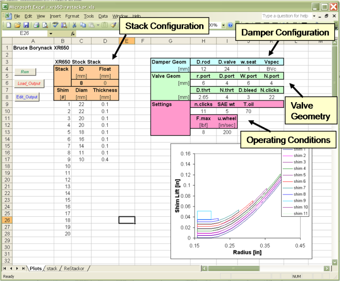
The parameters used in each of these sections are described below. After filling out the input file clicking the run button in the upper left hand corner executes the 11,000 lines of ReStackor code. The Load_Output button loads the calculation outputs back into excel. As the output file is loaded all of the plots in the ReStackor spreadsheet are updated with the current calculation results.
The excel macros that write the input file are linked to specific cell locations. So, on the "Plots" tab of the ReStackor spreadsheet, you should not add, move or relocate any of the cells.
![]()
Stack Configuration in ReStackor Input file
The stack configuration is simply a list of the diameter and thickness for each shim in the stack starting with the first shim at the valve face. Up to 50 shims can be used. The inside diameter for all shims in the stack is entered in the ID cell (c6). If the stack uses any float this is entered in cell (d6). All dimensions are in millimeters.
The stack deflection plot shows the stack structure and the thickness of each shim in the stack. This plot, generated from the ReStackor outputs, helps to insure the stack parameters entered are correct. If you miss type a shim diameter or thickness it will show up as a disruption in the stack structure.
![]()
Damper Configuration
There are two types of valves used in suspension systems. Mid-valves and base-valves. Base valves are generally located on the opposite end of the shock from the rod entrance and are typically used for compression damping. As the damper rod is forced into the shock, fluid is forced out of the shock through the base valve. Since the damper rod is a small diameter the fluid flow rate through the base valve is generally low.
The mid-valve is located on the end of the damper rod. As the damper rod is forced into the shock fluid flows through the face of the mid valve and fills in the area behind the mid-valve. On compression the entire face of the mid-valve is pressurized. On rebound only the annulus between the outside diameter of the valve and rod diameter is pressurized. Due to this difference in face area the forces generated by the mid-valve are different under compression and rebound.
The type of valve to be analyzed in a ReStackor calculation is specified through the Vspec keyword in the input file:
-
BVc: Base valve compression
-
MVc: Mid-valve compression
-
MVr: Mid-valve rebound
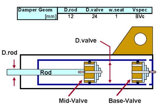
For the XR650 fork compression valve we are doing a base valve analysis so the keyword Vspec is set to BVc. D.rod is the damper rod diameter, D.valve is the valve outside diameter. All dimensions are in millimeters. The parameter w.seat is discussed below.
![]()
Valve Geometry
Damping rates produced by suspension systems are strongly influenced by the valve geometry. If you mistakenly input overly large or overly restrictive valve ports ReStackor will compute those inputs with impunity and your damping rates will be off. It is important to get the ReStackor valve geometry inputs right.
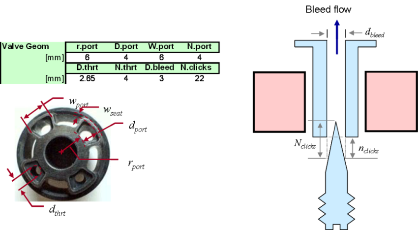
r.port defines the inner radius of the valve port and the inner radius where forces from the fluid flow through the valve port are applied to the shim stack face. d.port and w.port define the seat perimeter of the valve port. ReStackor uses these seat perimeter measurements to determine the available flow area between the valve face and shim stack. A larger perimeter provides more flow area and less flow resistance. w.seat defines the valve port seat width. This value is entered in the damper configuration block above.
N.port defines the number of valve ports. For the XR650 there are four ports. D.bleed defines the diameter of the clicker bleed port through the suspension valve. If the flow path of the bleed port has a smaller diameter flow restriction somewhere within the bleed port you need to use that diameter. N.clicks defines the total number of adjuster clicks from full open to closed. Full open is defined as the position where the tip of the needle enters the bleed port. If there are a bunch of clicks beyond that point they obviously do nothing to effect damping and should not be used in the value of N.clicks.
For most valve configurations, like the KTM valve pictured below, d.port and w.port define the flow area of the valve port as well as the valve seat perimeter. For open port configurations there is no port restriction and the value of d.thrt is set to zero as a flag to the calculations to ignore d.thrt.
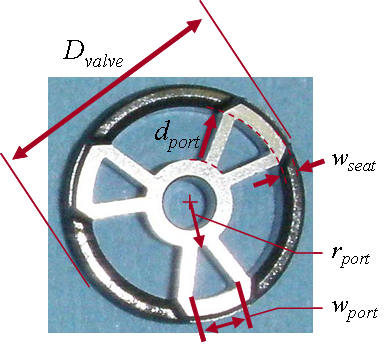
For special configurations, like the XR650 fork compression valve, the throat area of the valve port is smaller than the area defined by the valve seat perimeter. For these configurations d.thrt is used in the ReStackor inputs to define the minimum valve throat area. The stock XR650 fork compression valve has a valve throat diameter of 2.65 mm. In Borynack's picture above two of those valve ports have been drilled out to a larger diameter. N.thrt defines the number of throats, in this case there are four ports. ReStackor defines the number of valve port throats N.thrt separately from N.port to handle the special case where multiple valve side ports feed one common valve port.
![]()
Operating Conditions
The final input block "Settings" define the operating conditions for ReStackor calculations.
n.clicks defines the clicker setting, zero is closed. SAEwt defines the oil viscosity and T.oil defines the oil temperature in degrees Fahrenheit. With these inputs you can quickly change the clicker setting or the oil viscosity and click on the run button to see the effect of each parameter on the performance of the suspension.
F.max defines the maximum force applied to the shim stack for the stack deflection calculations of Shim ReStackor. The calculations compute approximately 20 points between zero and input value of F.max for use in producing the stack deflection and valve face flow area plots. The stack structure deflection plot, shown in the above figure, is computed at the input value of F.max. For crossover stack configurations you can run several calculations at different values of F.max to graphically display the point where the crossover gap closes.
u.wheel defines the maximum suspension velocity for ReStackor pro calculations. If the wheel velocity requested requires a stack force greater than the value specified by F.max ReStackor will internally compute additional stack deflection points to be consistent with the requested wheel velocity. The calculation outputs, however, display the stack deflections and valve face flow area at the value specified by F.max. This feature allows you to compute damping performance at high suspension velocities specified by u.wheel while examining the low speed deflection behavior of the stack specified by F.max.
![]()
Simple parametric calculations
With the input file set up parametric calculations with the ReStackor are easy. You can change the value of n.clicks to see the damping forces generated at different clicker settings. Change the SAE wt oil viscosity to see how many clicks stiffer or softer your suspension would be with those settings. Or paste in Borynack's stack configurations to compare damping rates for those stacks to the stock stack.
Keystroke examples of these parametrics are given further down in the XR650 sample application thread.
