

Needle Geom
![]()
ReStackor Needle Geometry Inputs
Bleed circuits typically use a blunt tipped needle with a tip diameter approximately 1/2 the bleed circuit throat diameter. This geometry produces a nearly linear change in area over the clicker range. This is the default ReStackor needle geometry.
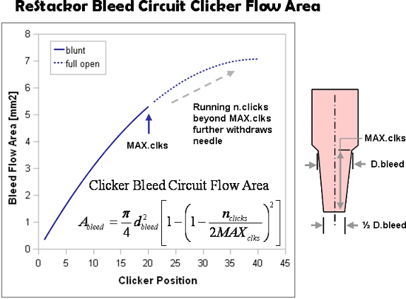
Other needle shapes can be modeled in ReStackor using a needle geometry input table which defines the needle diameter as a function of clicker position. Using table inputs ReStackor can match the clicker flow area of virtually any configuration.
ReStackor Needle Geometry Table Inputs
To run a needle geometry table both d.bleed and MAX.clks must be set to zero.
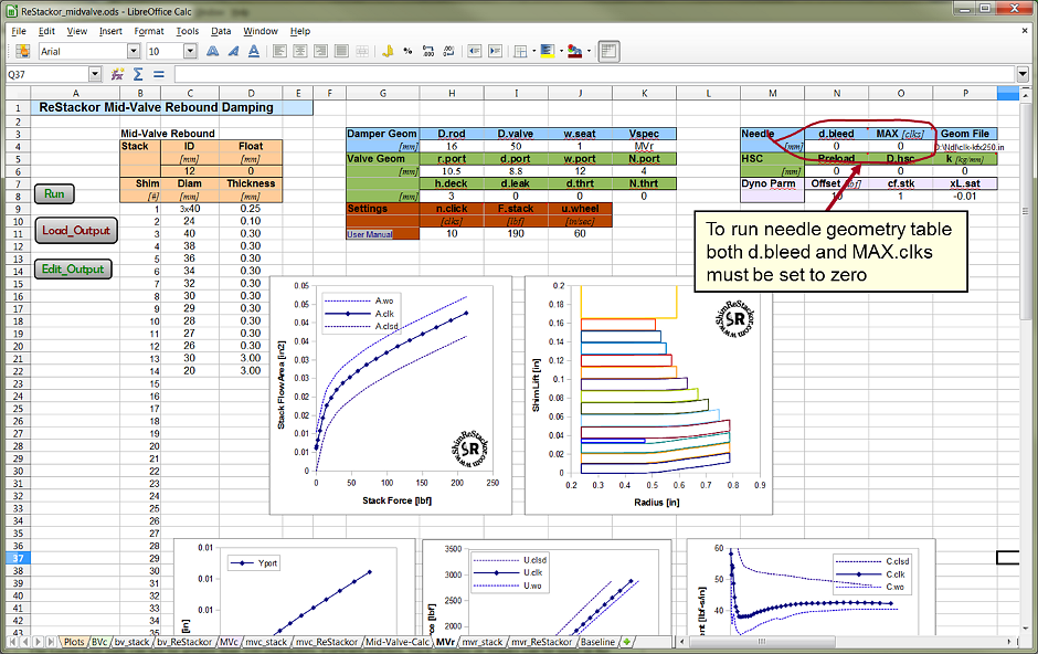
Setting d.bleed and MAX.clks to zero triggers ReStackor to look for the file path specified by the Geom.File parameter. The Geom.File path can not be greater than 100 characters. Forward slashes, back slashes or blanks can be used in the file path name. Examples:
-
C:/ReStackor/Work_Dir/Needles/sample_needle_geom.dat
-
C:\Users\My User Name\My Documents\ReStackor\My Needle Geometries\my custom needle.dat
The needle geometry table
has
the
following
format: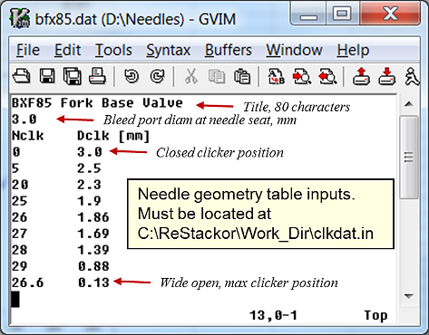
-
Line 1 : Title with a length up to 80 characters.
-
Line 2 : The needle seat/port diameter in millimeters.
-
Line 3 : Text string "Nclk Dclk [mm]"
-
Line 4 : List of clicker position and the corresponding needle diameter. Up to 100 entries can be used in the table.
-
End : The last entry defines the value of MAX.clks.
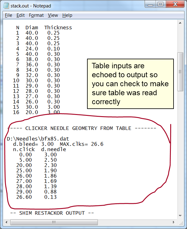
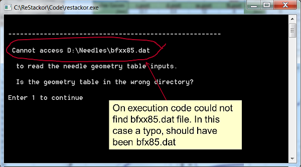
When ReStackor reads the needle geometry table the inputs are echoed to the output file. You should check the output file to make sure the table was read correctly.
If ReStackor can not find the file specified by the Geom.File path or can not read the format of the file the pop-up execution window will show and error.
Example Needle Geometries
The inputs to the needle geometry table are best demonstrated through example. The first step is to measure the needle and determine the needle diameter as a function of length measuring locations where the needle slope changes. You also need to know how far the needle tip moves per click of the adjuster. For the needle in this example 25 clicks are needed to move the needle from the seated position to the location where the needle tip is flush with the bleed port entrance. 4.2 mm of travel over 25 clicks works out to be 6 clicks/mm.
The above measurements define the needle geometry up to the point where the needle tip is flush with the bleed port exit . This table is adequate for most applications.
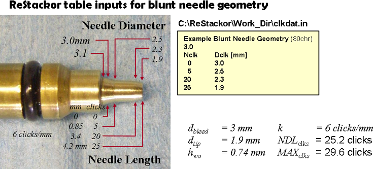
The final entry in the table, 25 clicks in this case, is the needle tip diameter at MAX.clks. This value defines the wide open clicker position flow area used in all of the ReStackor plots.
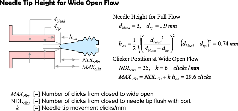
If you want ReStackor to model the full range of the clicker positions, including cases where the needle tip is outside of the bleed port, you need to determine the needle tip height where the bleed port runs full open. The full open height, h.wo, is the needle tip position where the tip no longer restricts the port exit. h.wo is defined by the relationships below.
For the needle geometry in this example the needle tip needs to be 0.74 mm above the bleed port so that the needle no longer restricts the port exit. The bleed circuit runs wide open at a clicker setting of 29.6 clicks from closed.
The next step is to determine the port exit flow area as a function of needle tip height, h, above the port. For this example the tip is flush with the bleed port at 25 clicks and the port runs wide open at 29.6 clicks. Substituting those clicker position into the equations below allows h to be determined as a function of clicker position. With the tip height known the value of d.eff can then be determined as a function of h. These values of clicker position and d.eff are then entered into the table. The example table below uses one click increments from 25 to 29.6 clicks, any clicker increment can be used.
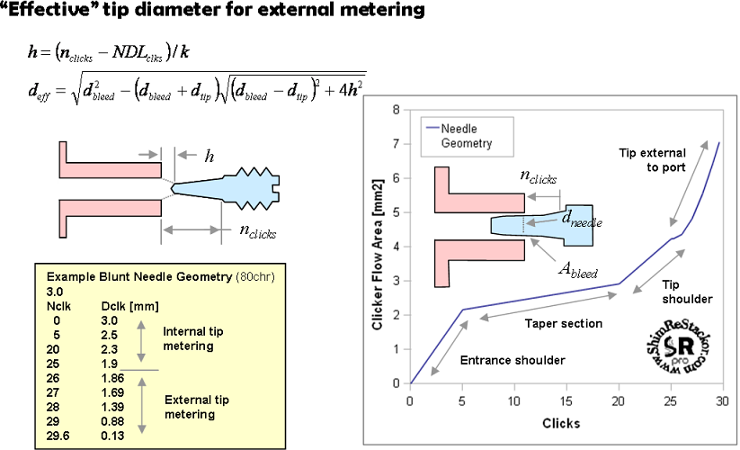
The needle in this example has 4 distinct clicker ranges. From zero to five clicks the steep entrance taper of the needle creates a large change in area as the needle is cracked open. From five to 20 clicks the gentle taper of the needle creates little change in flow area. Through this range friction loss along the long annular section between the needle and bleed port control the flow rate. From 20 to 25 clicks the rounded tip of the needle is extracted from the bleed port and from 25 to 29.6 clicks the needle is outside the port but still partially blocking the port exit. Once the needle tip reaches a distance of h.wo away from the port the bleed circuit runs wide open. Through this range of external metering small changes in clicker position produce a large change in bleed circuit flow area.
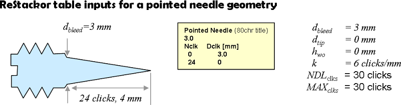
Pointed Needle
For a pointed conical needle the table inputs are much simpler. All that is needed is the diameter of the bleed port and the number of clicks to bring the needle tip flush with the port exit. Since the tip is sharp the bleed port runs full when the tip is flush with the exit. There is no external flow metering for this needle.
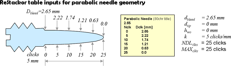
Parabolic Needle
To describe the contour of a parabolic needle several points along the contour are needed. ReStackor linearly interpolates the needle geometry between each point in the table. To smoothly describe the contour of a curved surface several measurement are needed along the needle length.
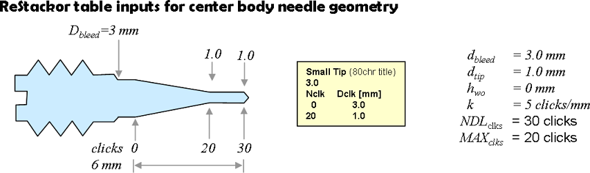
Small Tip Needle
Needles with a straight conical taper only need a couple of measurements to describe the needle geometry.
Flow
Area
Curves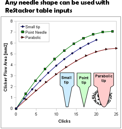
The geometry of a simple conical needle produces a nearly linear change in flow area across the range of clicker settings. Pointed needles and parabolic needles produce progressively smaller changes in flow area as the needle approaches the MAX.clks position.
Using table inputs ReStackor can accurate descriptions the bleed circuit flow area of any needle shape. All that is needed is a set of measurements that describe the needle diameter as a function of length and clicker position.
Summary Example
The first click moves the needle off of the 3.0 mm bleed port seat and flow is meter by the 2.8 mm shank diameter of the needle. At 22.8 clicks the tip diameter is reduced to 2.5 mm. Over the first 22.8 clicks there is little change in flow area for this needle. Flow rates through the bleed circuit for this needle geometry are controlled by friction losses through the narrow annular slot between the needle and bleed port over this 22.8 click range of the needle .
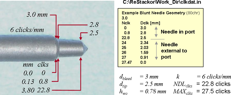
For clicker position beyond 22.8 clicks the needle tip is outside of the bleed port. The relationships below compute the needle tip height needed for full flow, h.wo, to be 0.78 mm. The needle tip was measured to be flush with the bleed port entrance at NDL.clks=22.8 so the full flow condition is reached at 27.5 clicks. Plugging in needle tip heights, h, from 0 to 0.78 in the relationships below computes the "effective" needle tip diameter, d.eff, to be the values shown in the table.
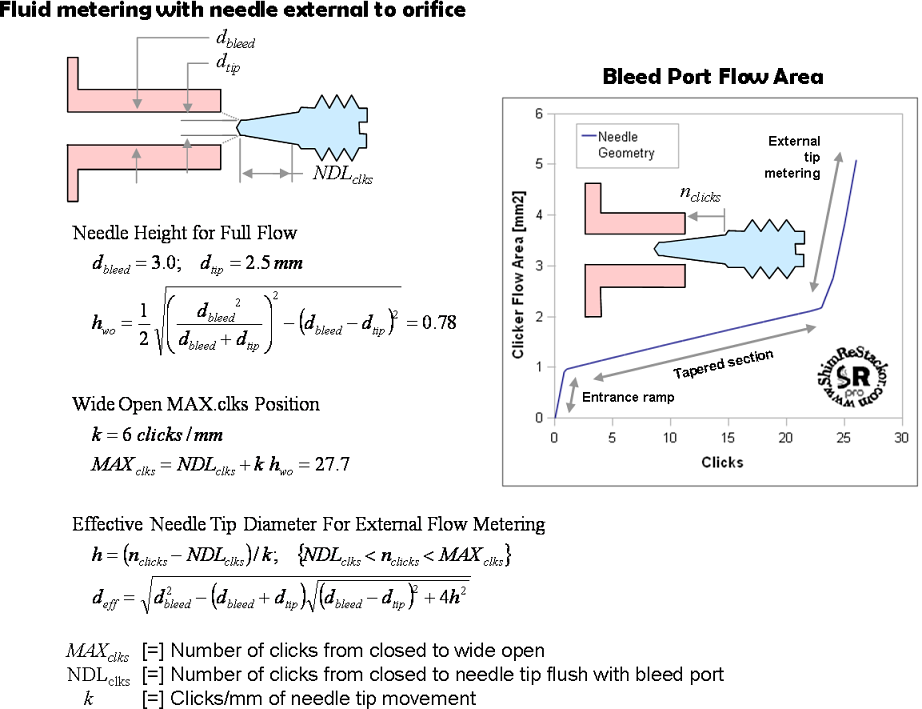
The needle flow area curve has a large area increase over the first click as the needle is moved off of the bleed port seat. Through the bulk of the clicker range from 1 to 23 clicks there is little increase in flow area. Through this range the bleed circuit flow rate is controlled by friction losses through the narrow annular slot between the needle and bleed port. At clicker positions beyond 23 clicks the needle tip is external to the bleed port and small changes in the needle tip position result in large changes in flow area.
