

Reservoir Pres
![]()
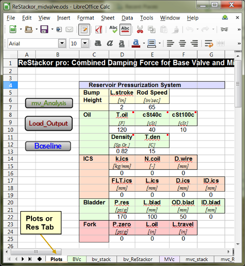
Reservoir Pressurization System
Reservoir Pressurization inputs are on the "Plots" or "Res" tab of ReStackor spreadsheets.
-
Bump Height: Max stroke depth and shaft speed for ReStackor calculations of the combined base and mid-valve damping force
-
Oil: Oil viscosity, density and temperature used in calculations
-
ICS, Bladder, Fork: Parameters describing the configuration of reservoir pressurization systems in ReStakcor calculations.
![]()
Bump Height:
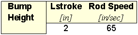
When you click on the "MV_Analysis" macro button ReStackor runs a set of calculations to determine the combined damping force of the base valve and mid-valve. Those calculations are run up to the shaft velocity specified by Rod Speed and up to the stroke depth specified by L.stroke.
-
L.stroke [=] Bladders, ICS systems and the gas pressure in open chamber forks all depend on stroke depth. ReStackor calculations start with the suspension at full extension and integrate over the stroke up to the stroke depth specified by Lstroke. Lstroke specifies the actual shaft stroke of the shock, not the wheel stroke.
-
Rod Speed [=] Maximum suspension velocity. ReStackor computes the combined compression damping force of base valves (BVc) and mid-valves (MVc) up to the shaft speed specified by Rod Speed.
![]()
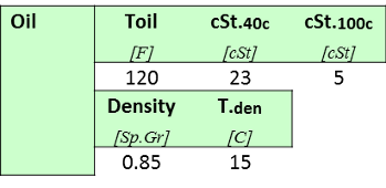
Oil Properties: Oil properties used for all calculations in the spreadsheet.
-
Toil [=] Shock absorber oil temperature in degrees Fahrenheit. Temperature effects on viscosity are evaluated in ReStackor using the Andrade relationship along with companion relationships for the oil density change with temperature.
-
cSt40c [=] Oil kinematic viscosity in centistokes at 40 centigrade [cSt@40C].
-
cSt100c [=] Oil kinematic viscosity in centistokes at 100 centigrade [cSt@100C].
-
Density [=] Oil specific gravity or density in g/cc
-
T.den [=] Reference temperature of oil density spec, usually at 15 or 20 deg C. The specific gravity of suspension fluids range from 0.80 to 0.95 with synthetic fluids at the higher end.

![]()
Reservoir Pressurization Systems
Gas pressurized bladders and Inner Changer Spring (ICS) systems are used in forks and shocks to suppress cavitation by pressurizing the shock chambers. Open chamber forks also use the gas pressure to augment spring force for bottoming control. The frames below define the ReStackor inputs for each system.
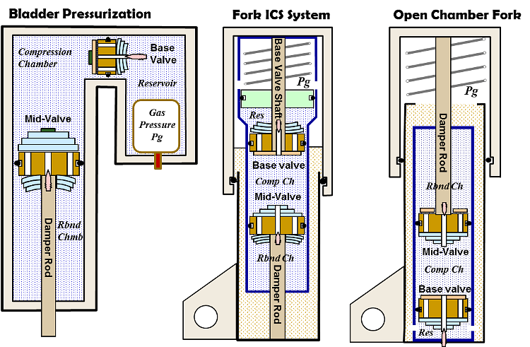
ReStackor models gas pressurized bladders and ICS systems in forks and shocks.
![]()
ICS Configuration:
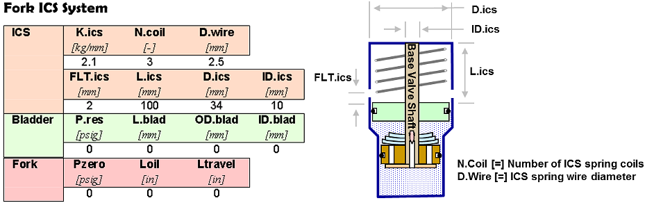
The ICS inputs specify the spring stiffness, float and piston diameter. To run an ICS configuration all of the bladder inputs must be set to zero.
Kics [=] Stiffness of ICS spring; [ kg/mm].
Ncoil [=] Number of coils in the ICS spring. ReStackor uses the number of coils and wire diameter to determine the spring coil bind travel limit. Push the piston beyond that point and it is going to crack. The fraction of ICS stroke used is reported in the ReStackor output as Nics.
Dwire [=] Wire diameter of ICS spring; [mm].
FLTics [=] ICS spring float at full suspension extension; [mm]. This parameter specifies the ICS piston motion necessary to engage the ICS spring. Negative float specifies spring preload.
Lics [=] ICS chamber length; [mm]. To specify and open chamber ICS Lics must be set to zero.
Dics [=] ICS piston diameter; [mm].
ID.ics [=] Shaft hole diameter in ICS piston; [mm]. For a typical configuration the base valve support shaft passes through the ICS piston. This parameter specifics the shaft diameter and is used to determine the pressurized face area of the ICS piston.
Pzero [=] Pzero in the Fork section defines the initial ICS chamber pressure at full extension of the suspension; [psig].
Closed chamber ICS: (Lics= chamber length) The ICS spring length plus float define the Lics chamber length. The initial gas pressure at full extension is set by the Pzero input in the Fork section. The ICS gas pressure increases as the piston compresses through the stroke. In a closed chamber ICS the gas pressure is unaffected by the fork chamber pressure.
Open chamber ICS: (Lics= 0) For an open chamber ICS vented to the fork gas chamber the values of Pzero, Loil and Ltravel defined in the Fork section determine the ICS gas pressure as a function of stroke position. The combined fork gas pressure plus ICS spring force define forces acting on the ICS piston.
![]()
Bladder Configuration: Specifies the reservoir bladder configuration used in a fork or shock. To run a bladder configuration all of the Fork and ICS inputs must be zero.
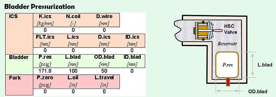
P0.blad [=] Initial bladder pressure at full suspension extension; [psig].
L.blad [=] Bladder length; [mm].
OD.blad [=] Outside diameter of bladder; [mm].
ID.blad [=] Normally zero. For a fork, the bladder may have the base valve support shaft running through the bladder. ID.blad is the diameter of the shaft for use in computing the gas volume in the bladder; [mm].
![]()
Oil Level Open Chamber Fork
The
"Fork" input block defines the initial bleed pressure and oil height
with the fork at full extension. To run an open chamber fork all ICS and Bladder inputs must be
zero.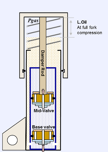 The value of P.zero specifies the initial pressure at full extension
for both open and closed chamber forks.
The value of P.zero specifies the initial pressure at full extension
for both open and closed chamber forks.
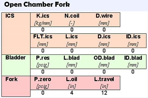
Pzero [=] Initial bleed pressure of fork at full suspension extension; [psig].
Loil [=] Oil height in fork measured from top of fork tube with the fork fully compressed; [in].
Ltravel [=] Length of fork travel; [in].
