

Response
![]()
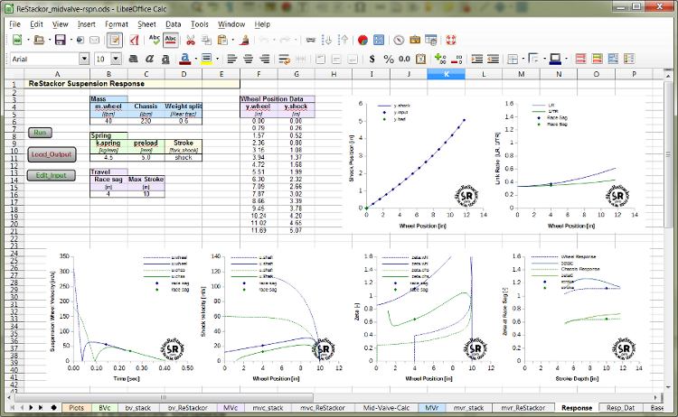
Output File: ReStackor Suspension Response Calculations
Outputs of ReStackor suspension response calculations are on the "Resp_Dat" tab of ReStackor mid-valve spreadsheets. Definitions of each output parameter are given below.
Wheel and chassis bottoming
ReStackor suspension response calculations determine the wheel bump velocity required to reach the "Max Stroke" position specified in the spread sheet inputs. The wheel stroke starts from the suspension normal ride height specified by the input parameter “race sag”. The chassis bottoming stroke assumes the bike is landing after a free fall and starts from full extension. The calculations account for the effect of link ratio, shock gas force, spring force and damping.
Suspension position and velocities are tabulated in the “Resp_Dat” tab of the spreadsheet. The first block of output data describes the wheel position through the compression stroke. The second block of data describes the wheel rebound stroke. The third block describes the chassis compression bottoming stroke and the final fourth block describes the chassis rebound stroke. Each block is separated by a header describing the variable name and units. In each output block the first line records the value at race sag for plotting purposes.
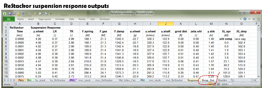
ReStackor suspension response output parameters
Time [=] Elapsed time from start of suspension stroke
y.wheel [=] Wheel position measured from full extension
LR [=] Suspension link ratio. Ratio of shock to wheel motion for an incremental change in y.wheel at the current suspension position
TR [=] Travel ratio. Ratio of wheel to shock travel at the current suspension position
F.spring [=] Spring force at wheel
F.gas [=] Shock gas force at wheel
F.damp [=] Shock damping force at shock shaft
a.wheel or a.chs [=] Wheel or chassis acceleration at current stroke position
u.wheel or u.chs [=] Wheel or chassis velocity at current stroke position
u.shaft [=] Shock shaft velocity
zeta.whl [=] Suspension response zeta coefficient at current stroke position
y.shk [=] Shock shaft position
XL.spr [=] Spring plus shock gas force at wheel axel. XL intended as an abbreviation for axel
XL.dmp [=] Damping force at wheel axel
![]()
Stroke averaged zeta response coefficient
Following the suspension response outputs ReStackor outputs the instantaneous and stroke averaged zeta value for the rebound stroke of both the wheel and chassis. Output parameters are described below:
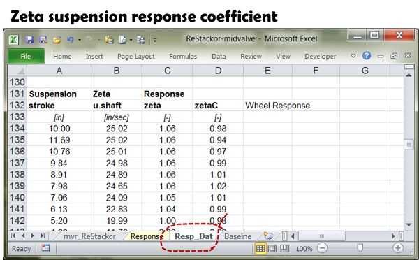
Suspension response zeta coefficient outputs:
stroke [=] Maximum stroke depth measured from full extension
u.shaft [=] Maximum shock shaft velocity in the rebound stroke
zeta [=] Instantaneous rebound zeta value on return to race sag
zetaC [=] Stroke averaged zeta value giving same response time and final velocity as actual suspension
![]()
Damping Force
ReStackor suspension response calculations use the computed compression damping force for the shock extracted from the "Mid_Valve_Calc" output tab and rebound damping force from the "mvr_ReStackor" output tab. Those values are echoed in the suspension response output data along with the rebound/compression damping ratio. The output parameters are defined below:
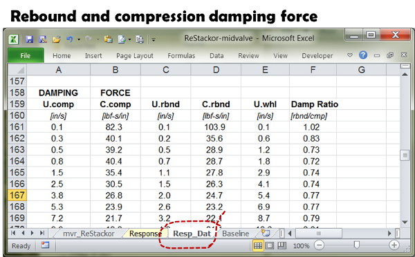
Shock damping force outputs:
U.comp [=] Shock shaft compression velocity
C.comp [=] Shock compression damping coefficient defined as the shocks compression damping force divided by shaft velocity
U.rbnd [=] Shock shaft rebound velocity
C.rbnd [=] Shocks rebound damping coefficient
U.whl [=] Suspension wheel velocity
Damp Ratio [=] Shocks rebound/compression damping ratio at the suspension wheel velocity specified by U.whl
![]()
Maximum velocities in shock compression and rebound strokes
ReStackor suspension response calculations record the maximum shock shaft velocity in the compression and rebound strokes for a full suspension stroke that reaches the maximum stroke position specified in the input link ratio curve. Those velocities are shown in the Max Damping Force output table below.
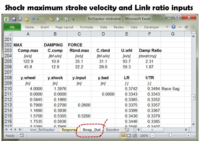
Maximum shock shaft stroke velocities
Comp.max [=] Maximum shock shaft compression velocity to reach the stroke limit of the input link ratio curve. The first line specifies maximum velocities for the wheel bottoming stroke and the second line specifies the limit of the chassis bottoming stroke
C.comp [=] Shock compression damping coefficient at the maximum shaft velocity
Rbnd.max [=] Maximum shock shaft rebound velocity for a full stroke specified by the limits of the input link ratio curve. The first line specifies the maximum velocity occurring in the rebound stroke after wheel bottoming and the second line specifies the maximum rebound velocity after chassis bottoming
C.rbnd [=] Shock rebound damping coefficient at the maximum shaft velocity
U.whl [=] Maximum rebound stroke suspension wheel velocity for the stroke depth specified by the "Max Stroke" input parameter. First line give the maximum velocity during the wheel response stroke and the second line gives the chassis stroke
Damp Ratio [=] Rebound/compression damping ratio at each U.whl rebound velocity
Suspension link ratio
The output block lists the wheel and shock position input data used to determine the suspension link ratio along with the link ratio and travel ratio determined from the input values. Data points in the input that are more than 5% off of the average curve are listed in the y.bad output column and plotted as green data symbols on the link ratio plot.
y.wheel [=] Wheel position measured from full extension
y.shock [=] Shock position measured from full extension
y.input [=] Shock position input value
y.bad [=] y.input values that are more than 5% off of the average link ratio curve
LR [=] Suspension link ratio defined as the incremental change in shock position for an incremental change in wheel position
1/TR [=] Suspension travel ratio defined as the suspension wheel position divided by the shock position. Outputs are 1/TR for plotting purposes.
![]()
Race sag spring force
Based on the input chassis weight and rear/front weight split ReStackor determines the suspension free sag and race sag weight. Output parameters are defined below:
Free sag [=] Free sag necessary to support the chassis weight
Chassis [=] Chassis free sag weight based on input chassis weight and weight split
Race sag [=] Echoed input value of Race sag
Race wt [=] Force on wheel for input value of race sag, spring rate and link ratio. If calculations are for a fork Race wt is weight on front wheel. If calculations are for a shock Race wt is the weight on the rear wheel.
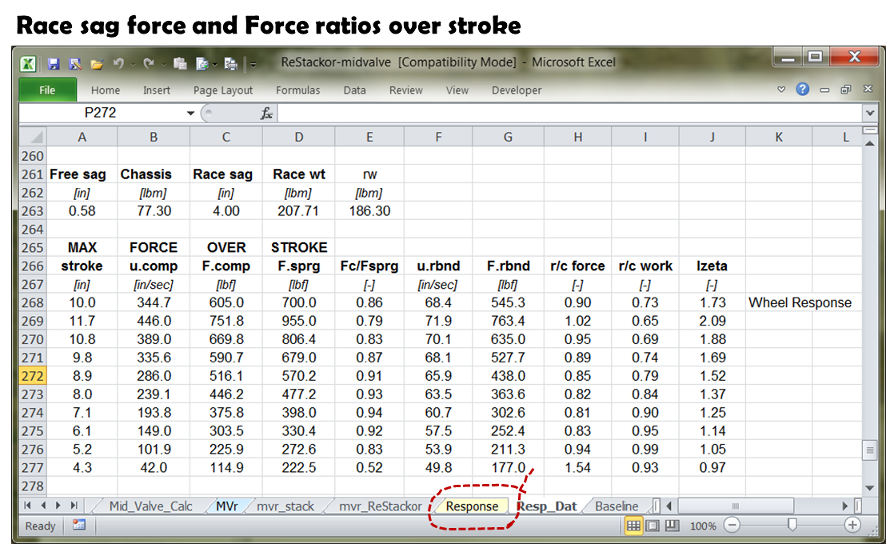
ReStackor parametric calculations to determine zeta values over the stroke depth range also record the maximum suspension velocities and damping force at each stroke depth. Those values are output along with the rebound/compression damping force ratio and work done over the stroke.
stroke [=] Suspension stroke depth
u.comp [=] Maximum suspension velocity in compression stroke
F.comp [=] Peak compression damping force through stroke
F.sprg [=] Suspension peak spring force at specified stroke depth
Fc/Fsprg [=] Ratio of peak compression damping force to peak spring force
u.rbnd [=] Maximum suspension velocity in rebound stroke
F.rbnd [=] Maximum rebound damping force over specified stroke depth
r/c force [=] Ratio of peak compression damping force to peak rebound damping force
r/c work [=] Ratio of work over rebound stroke to work in compression stroke
Izeta [=] Instantaneous zeta value at the maximum rebound stroke velocity
