

Fluid Dynamics

Fluid Dynamics
There are eleven tunable features in the fluid circuits of a shock, all tunable by the fluid dynamic models of ReStackor pro. If each feature was modified to be fluid dynamically perfect there would be no flow losses through the fluid circuits and the shock absorber would produce no damping. Tuning damping performance is the process of tuning each geometric feature in the flow circuits to produce controlled flow losses and a controlled damping force over the entire range of suspension speeds.
ReStackor pro uses fundamental fluid dynamics models to evaluate port entrance losses, area expansion losses, port turning losses, jet turning losses and wall friction. These physics based models relate the flow area and geometric features of each component to flow losses and allow you to tune each component for the control of flow loss to shape the shock absorber damping force curve to produced the damping characteristics you want. Accurate control and tuning of flow losses through the fluid circuits of a shock is the key to controlling damping force and the shape of the damping force curve produced by a shock absorber.
![]()
ReStackor pro models 11 tunable features of the valve flow circuit
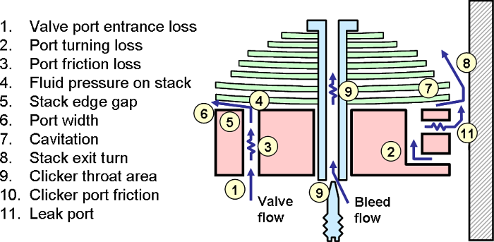
Flow losses through the suspension circuits are caused by port entrance losses, area expansion losses, port turning losses, jet turning losses and wall friction. The fluid dynamic models in ReStackor pro addressing each one of these flow losses are reviewed in the frames below.
1.
Valve
port entrance loss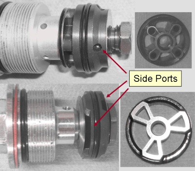
There are two styles of valve ports used in suspension systems. Discrete side entrance ports drilled into the side of the valve or annular slots created by the gap between valve ports and the stack. For either style the fluid flow area at the entrance is the critical parameter controlling flow losses. Flow losses at the port entrance are caused by viscous interactions in the fluid as the fluid accelerates from the stagnate conditions of the reservoir to the high velocities in the valve port. ReStackor uses Reynolds number based flow loss coefficients to quantify these losses.
![]()
2.
Port Turning
Loss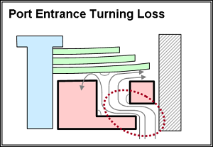
Downstream of the entrance additional flow losses are generated in the valve ports due to turning the flow. These losses are created by a combination of momentum loss due to changing the direction of the flow and flow separations at the corner for higher suspension velocities. ReStackor estimates turning losses using the flow area of the entrance and valve port based on a sharp 90o bend. This simple model has been demonstrated to adequately model turning losses in suspension systems through comparison with dyno test data. The turning losses can be reduced by modifying the piston valve to increase the port entrance area or the valve port diameter. ReStackor pro models both of these effects. This allows you to use ReStackor calculations to experiment with valve port geometry modifications and evaluate effects of those modifications at different suspension speeds before committing to irreversible modifications of the valve port geometry.
Example ReStackor calculations evaluating effects of valve port restrictions are included in the XR650 sample application page of the ReStackor web site.
![]()
3. Friction Loss
ReStackor uses real world commercial suspension fluid viscosity data
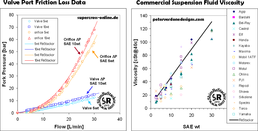
ReStackor uses a Reynolds number based skin friction model to compute pressure losses through the valve ports. These Reynolds number based models compute the effect of port geometry, flow velocity, fluid viscosity and temperature on friction losses through the fluid circuits. Supercross-online.de has tested yz250 fork valves to determine the flow resistance and friction losses in the valve ports. ReStackor matches this data over the tested velocity range and matches the effect of fluid viscosity changes on the flow resistance of the valve. Basic fluid dynamics allows ReStackor to accurately compute viscous pressure losses in the fluid circuit of a shock and account for a wide range of suspension fluids.
Skin friction and fluid viscosity relationships in ReStackor anchored to real world data and reliably compute the effect of fluid viscosity changes on damping performance.
ReStackor uses real world viscosity data for suspension fluids
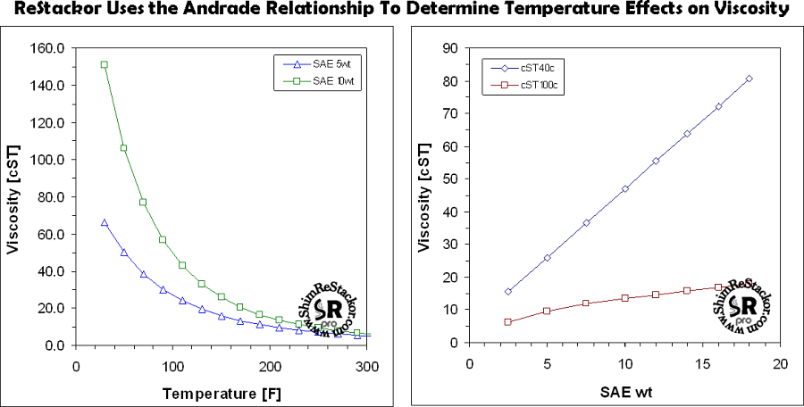
Peter Verdone has compiled an excellent data base of the viscosities of commercial suspension fluids. ReStackor pro uses Verdone’s Silkolene viscosity data to establish the relationship of SAE wt to fluid viscosity. Effects of fluid temperature on viscosity are corrected using the Andrade equation. This allows ReStackor to match reported viscosity data at cSt@40c and cSt@100c as well as reliably compute viscosities at room temperature or the high fluid temperatures occurring in the shock under hard use (more).
Temperature effects on fluid viscosity are computed in ReStackor using the Andrade relationship to accurately compute viscosities at high fluid temperatures.
Accurate modeling of fluid viscosity allows ReStackor pro calculations to accurately compute skin friction losses in the valve flow circuits over the entire range of suspension speeds and operating temperatures. This allows ReStackor to reliably compute flow rates through suspension bleed circuits and accurately reference shim stack changes in terms of how many clicks stiffer or softer each change will be.
![]()
4.
Fluid Pressure On Stack
Face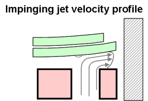
Jets from the valve port deflect off of the shim stack face and exit the thin annular gap between the shim stack and valve face. Jet stagnation at the impingement point cause the boundary layer to reinitialize resulting in high skin friction for the flow across the shim stack face.
Reinitializing the flow at the stagnation point also creates distortions within the fluid velocity profile and increased flow resistance at the valve edge gap. ReStackor pro uses the impinging jet velocity profiles of Blevins’ “Applied Fluid Dynamics Handbook[1]” for description of the velocity profile resulting from jet impingement.
Forces produced by jet impingment are a function of the jet velocity and continuously changing over the range of wheel speeds. Suspension valves using large ports produce lower port velocities and reduced jet impingement effects. Modeling jet impingement using basic physics allows ReStackor to account for the fluid dynamic effects of port geometry in a natural way.
[1] Blevins, R.D.,"Applied Fluid Dynamics Handbook", Krieger Pub, Malabar, Florida 2003.
![]()
5.
Stack
Lift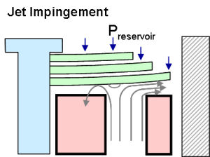
Shim stack lift on the valve face is caused by a combination of static pressure and jet impingement forces. At low suspension speeds static pressure is the dominate force controlling stack lift. As suspension speeds increase jet impingement become progressively more important as well as the flow losses incurred in the valve flow circuits to generate the high momentum jet. Accurate calculation of damping rates requires careful accounting of the jet impingement forces and the effect of these forces in deflecting the stack.
Thorough modeling of the stack structure stiffness and accurate accounting of the jet impingement forces allows ReStackor to accurately compute flow losses created by acceleration of the fluid through the shim stack gap at the valve edge. ReStackor pro has been demonstrated to accurately account for these effects through comparison with dyno data .
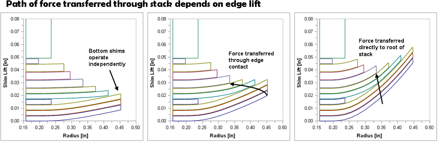
Computing the damping force produced by shock absorbers requires accurate fluid dynamics models as well as accurate shim stack structure analysis to compute the stack face flow area.
![]()
6.
Valve
Port
Width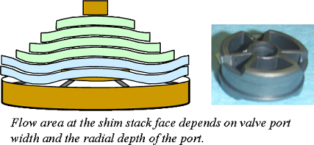
Wide valve ports increase the flow area at the shim stack perimeter and decrease the flow resistance of the valve. The fluid flow area at the stack perimeter depends on both the radial and circumferential width of the valve port. ReStackor carefully integrates the flow area produced by stack deflection along the valve port perimeter and radial spokes of the valve to account for the subtle effects of stack taper changes on the bend profile of the stack face shim.
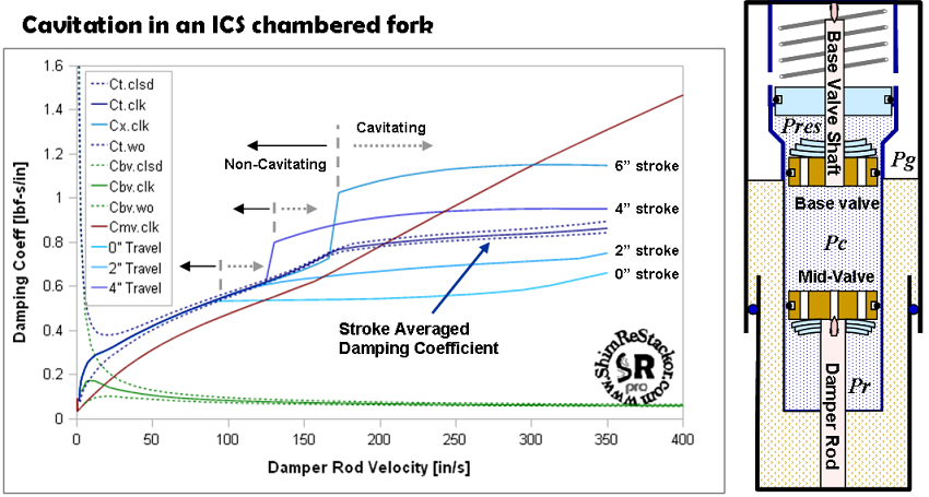
7. Cavitation
Controlling cavitation in a shock simply requires pressures in the fluid circuits to be greater than the vapor pressure of the fluid. While conceptually simple, confusion over the stiffness of shim stacks, pressure drop through the fluid circuits and back pressure produced by bladder or ICS systems make evaluation of cavitation limits difficult. Since ReStackor models the physical flow processes occurring within the guts of a shock it is a simple mater to examine the physical flow processes occurring through each component, determine the cavitation limit and tune each component of the shock to operate within the cavitation limits. What is often referred to as a complex interaction of cavitation is reduced to solution of a simple arithmetic relationship: ( more )
![]()
8.
Stack
exit turn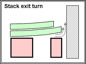
After exiting the valve the flow impinges on the shock body and turns to enter the downstream fluid reservoir. ReStackor calculations account for this turning loss and the losses created as the fluid accelerates through the annular gap between the shock tube body and the largest shim. Changes in diameter of the stack face shim or backing shims in the stack effect this pressure loss.
![]()
9. Bleed circuit "clicker" flow
The default ReStackor needle geometry uses a simple cone shaped needle with a blunt tip equal to 1/2 of the bleed port diameter. The blunt tip blocks 25% of the flow area at the wide open clicker position and produces a nearly linear area profile over the range of clicker settings.
The default clicker needle geometry in ReStackor uses a blunt tip needle tip. Other needle tip geometries can be modeled using input tables.
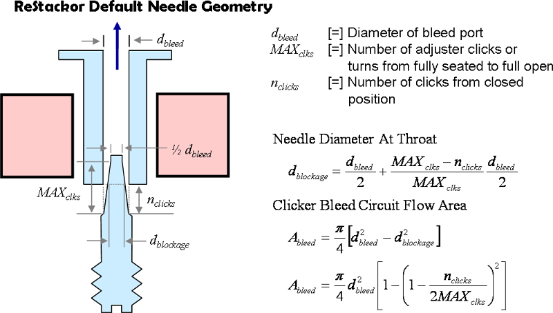
Needle geometries different from the default taper, pointed needles or parabolic needle shapes can be modeled in ReStackor using input tables to describe the needle diameter as a function of clicker setting. The process is illustrated in the ReStackor users manual .
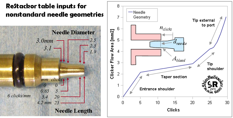
Table inputs allow any needle shape to be modeled in ReStackor.
10. Bleed Circuit Flow Losses
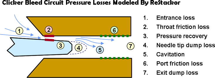
There are seven elements to the flow losses occurring through the clicker bleed circuits:
-
Entrance loss: Velocity gradients between the converging streamlines at the entrance to the clicker throat create flow losses. These flow losses are viscous based. Higher oil viscosities increase the entrance flow loss.
-
Throat friction loss: The minimum flow area at the clicker throat creates the highest velocities and the highest skin friction loss. Friction losses at the throat depend on the flow velocity, oil viscosity and clicker position. At the near closed position the high surface area of the combined port and needle perimeter create high friction losses.
-
Pressure recovery: Downstream of the throat the expanding flow area of a tapered needle geometry decelerates the flow. Pressure recovery through this region depends on the flow velocity, boundary layer thickness, friction losses and the needle taper angle. High flow velocities through the clicker circuit created by stiff shim stacks can cause the flow to separate and suddenly increase the flow losses through the clicker circuit.
-
Needle tip dump loss: At the needle tip the flow separates from the needle surface and creates a loss known as a dump loss. The magnitude of the pressure loss depends on the flow velocity at the needle shoulder which in turn depends on the pressure recovery through the tapered needle section. Stiff shim stacks force more flow through the clicker bleed circuits producing higher flow velocities and a higher dump loss at the needle tip.
-
Cavitation: Cavitation creates the psst, psst sound frequently heard from suspensions when rolling over small bumps. Cavitation in the bleed circuits is caused by stiff shim stacks, high flow velocities and high area expansion ratios from the needle taper or a blunt needle tip. Once cavitated the cavitation bubble will crawl up the needle taper to the point that balances bleed circuit flow losses with the vapor pressure of the hydraulic fluid. The ReStackor bleed circuit flow model include these cavitation effects and model the flow losses occurring through the bleed circuit when driven beyond the cavitation limit.
-
Port friction loss: Downstream of the needle tip the flow expands to the bleed port area reducing the flow velocity and wall friction losses through the remainder of the bleed circuit. ReStackor uses Reynolds number based skin friction coefficients to determine fluid velocity and viscosity effects on wall friction losses including both laminar and turbulent skin friction losses.
-
Exit dump loss: At the bleed port exit the flow spills into the downstream fluid reservoir. This sudden area expansion produces a dump loss similar to the flow losses occurring at the needle tip.
Bleed
Circuit
Dyno
Data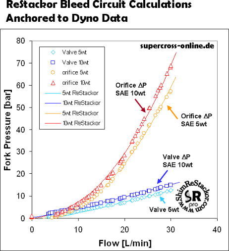
The capability to accurately compute flow rates and pressure drops through a flow restriction is a basic fluid dynamic problem dating back to development of the Bernoulli equation in the 1700’s. Industry places a huge importance on accurate fluid metering and has spent huge development efforts to produce a set of fluid dynamic relationships capable of accurately computing flow rates through flow restrictions. Relationships developed through these efforts account for effects of flow geometry, orifice length, flow velocity as well as fluid viscosity and are capable of accurately computing flow rates from ultra low to ultra high suspension velocities. ReStackor uses these well anchored Reynolds number based relationships to compute flow rates and pressure drops through the bleed circuits. The calculations have been verified through dyno tests of real suspension hardware to accurately compute flow rates and pressure drops through orifice bleed circuits and accurately compute effects of fluid viscosity changes on bleed circuit flow rates.
![]()
11. Valve Leak Ports
Some suspension valves use leak ports to control low speed damping forces. Leak ports are typically small 1 to 2 mm ports drilled in the side of one valve port. port.
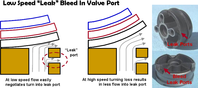
Leak ports are sometimes used in one valve port for control of low speed damping.
At low speed fluid velocities in the port are small and the flow can easily negotiate the turn into the leak port. Under these conditions the leak port is fully active. At high speed the high fluid velocities in the valve port can not negotiate the 90 degree turn into the leak port. This results in progressively lower flows through the leak port as suspension speeds increase. Large valve ports decrease the port velocity and keep the leak port active over a large range of suspension velocities.
The above problem of flow branching in a fluid circuit is a well studied problem frequently occurring in industrial fluid systems. ReStackor uses the fluid dynamic side port branching relationships of Blevins to determine flow rates through the leak port. For suspension systems this problem becomes somewhat more complex due to interaction of the leak port with the stiffness of the shim stack. Stiff shim stacks increase the pressure in the valve port and force more fluid through the leak port. The fraction of the flow exiting through the leak port becomes a complex function of the suspension velocity, valve port flow area, stiffness of the shim stack, fluid viscosity and leak port area. Shim stack changes not only effect damping but also the fraction of fluid exiting through the leak port.
[1] Blevins, R.D.,"Applied Fluid Dynamics Handbook", Krieger Pub, Malabar, Florida 2003.
![]()
Mid-valves and Base valves
There are two types of valves used in suspension systems: mid-valves and base-valves. The relationship of oil flow rate through the valve and damper rod speed are different for these two types of valves. ReStackor pro uses keywords BVc, MVc and MVr to specify the different valve types and the direction of flow through the valve. The differences in flow rates and its impact on damping forces produced by base valves and mid-valves is discussed here .
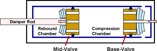
ReStackor models both mid-valves and base valves used in suspension systems.
![]()
Fluid dynamic flow losses
ReStackor pro uses basic physics and fluid dynamics to account for pressure losses and flow restrictions in the fluid circuits of a shock absorber. These physics based models describe the effect of each geometric feature of the shock on pressure losses and the damping force produced by the shock. The models allow you to experiment with modifications to each geometric feature, compute the change in damping force through modification of that feature, learn the influence each component has on damping performance of the shock and tune that component to achieve the damping force and damping profile that you want.
When tuning a shock there are frequently multiple ways to achieve the same effect. ReStackor gives you the capability to investigate each of those options to chose the option that is easiest to implement.
