

Shim Stiffness

Shim Stiffness
ReStackor integrates Hooke's law and Young's modulus of elasticity through the curvilinear coordinates of a shim to arrive at relationships describing shim stiffness following the same process used in development of the flat disk deflection formulas and Belleville spring equations. At high edge lift strain induced in the shim material cause the stack to distort or "potato chip". Those distortions in the stack structure relieve internal strain and result in an effective stack stiffness that is less then expected by the flat disk deflection formulas. The ReStackor relationships for shim stiffness and stack structure distortions have been verified through comparison with high speed dyno data at suspension velocities up to 550 in/sec. Those velocities are well beyond operation limits of conventional shock absorbers but critical in defining the performance of motorcycle forks where square edge impacts can produce those velocities.
Spring Stiffness
Hooke's law and Young's modulus of elasticity form the basis of all spring deflection formula and define spring stiffness in terms of the basic physical properties of the metal. As long as the local value of strain is below the metal yield strength the spring will return to its original position. Exceeding the yield strength causes the spring to become permanently bent.

Applying the above relationships to define the spring constant of a steel bar requires definition of a neutral bend axis. Material above the neutral axis is stretched during bending and material below the axis is compressed. By dividing the bar into differential slices the bending strain in each analysis element can be evaluated and integrated over the bar length to define the overall spring constant.
Force balance for bending of a steel plate is developed around a neutral bend axis. Material above the neutral axis is stretched, material below is compressed.
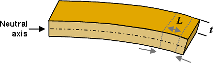
Compression of the material below the neutral axis causes the width of each analysis element to increase and stretching of the material above the neutral bend axis causes the width to decrease. Those transverse motions induce additional strain in the spring material increasing the effective spring stiffness. The change in width when the bar is compressed or stretched is a fundamental property of the crystal structure of the material and measured by Poisson's ratio in structural analysis theory.
For the circular geometry of a shim the force balance is drawn around a pie shaped element and the deflection stiffness determined through integration of the differential force balance examining the forces transmitted through each circumferential element of the pie slice. The circular geometry focuses forces applied at the outside edge into the tip of the pie slice where there is less material to react the applied force. That makes the center of the shim the most likely area to be stressed beyond the yield point .
Shim stiffness force balance. Curvilinear coordinates focus applied edge force on center of shim.
Integration of the stiffness of the annular elements of the pie slice through the curvilinear coordinates of a shim turns out to be a complex problem of integral calculus and analytic geometry. The equations have been worked out by General Motors engineers Almen and Laszlo1 in 1936 to form the Belleville spring and flat disk deflection formula. Simplified versions of Almen and Laszlo's relationships are available in copyrighted form at various locations on the net.
Of those sources, MitCalc offers the Belleville equations for purchase in spreadsheet form for easy design of Belleville springs and calculation of spring constants.
1) Almen, J.O. and Laszlo, A.,"The Uniform-Section Disk Spring," Trans. ASME, v.58, 1936
Belleville
Spring Stiffness
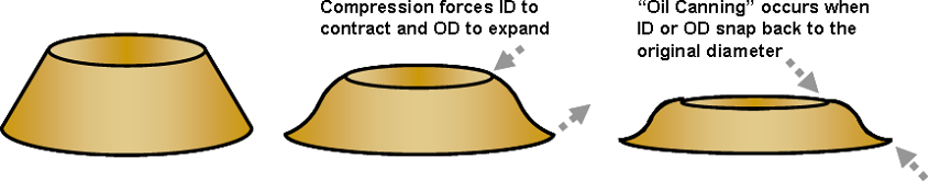
Belleville springs produce a digressive spring force curve. Understanding the cause of the digressive curve shape requires some familiarity with the operation of an old fashion oil can. On an old fashion oil can has a flexible bottom. Pressing on the bottom squirts oil out the top. As the bottom is deflected further the can eventually "pops" into a concave shape. The point where the bottom pops into a concave shape is referred to as "Oil Canning". At the point where the bottom surface "oil cans" the spring stiffness is reduced resulting in a digressive spring force curve.
"Oil Canning" is a central feature of the spring force curve produced by Belleville springs. Crushing the initial cone shape of a Belleville spring into a flat disk forces the inside diameter of the washer to contract and the outside diameter to expand. Distortions of the sidewall eventually allow the inside diameter to snap under the sidewall in an effort to return the top of the spring to its original diameter. The point where the inside diameter pops under the sidewall "Oil Cans" the washer. When the washer starts to "oil can" the spring force is reduced producing a digressive slope in the Belleville spring force curve.
Belleville spring "Oil Canning" occurs when shim ID snaps under sidewall producing a digressive spring force curve.
A
key feature of the Belleville spring equations is the capability of the
equations to model
the "Oil Canning" process. The
stroke depth where the spring "Oil Cans" is a function of the sidewall
thickness; inside and outside diameter; and initial
cone height. For small cone heights little stress is
developed on the inside diameter during crushing of the spring and the spring will
not "Oil Can". As the cone height increases the stress
on the top of the cone increases as well as the degree of "Oil Canning". At high cone heights a Belleville spring will
actually produce a negative 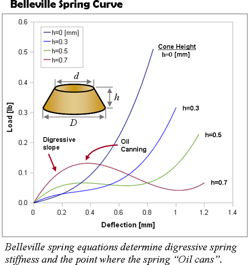 region in the spring force curve.
The negative slope marks the point where the ID of the washer has snapped under the sidewall.
When that happens the spring will stay in that distorted position until you push it
back through the negative slope region.
region in the spring force curve.
The negative slope marks the point where the ID of the washer has snapped under the sidewall.
When that happens the spring will stay in that distorted position until you push it
back through the negative slope region.
The capability to design the point where Belleville springs "Oil Can" gives spring designers the capability to create complex spring force curves. Through control of the initiation and magnitude of "Oil Canning" the digressive portion of the spring force curve can be designed to produce specific effects. This is the central feature that originally attracted the General Motors engineers Almen and Laszlo to investigate Belleville springs with the vision of replacing coil springs in automobiles with Belleville spring stacks designed to produce sophisticated spring force curves.
The digressive force curves produced by Belleville springs are created by distortions generated when the initial cone shape of a Belleville spring is crushed into a flat washer. Those distortions do not occur in the reverse process when a flat disk is deflected into a cone shape. The digressive spring force curves produced by Belleville springs are generally inapplicable to the stiffness of flat shims used in suspension systems.
![]()
Flat Disk Deflection
The force balance used in development of the Belleville spring equations can be redrawn around a flat disk and the relationships describing the spring stiffness of flat disk deflections derived following the same process used for Belleville springs. Steps of the process are outlined on eFunda. The resulting flat disk spring stiffness formula is identical to the Belleville spring equation with the simple substitution of a zero initial cone height. Due to the similarity of the relationships you often see the Belleville spring stiffness formula used and referred as the flat disk deflection formula.
The flat disk spring stiffness formula restrict all forces to be reacted within the plane of the shim, this restriction results in a progressive spring force curve with increasing edge lift.
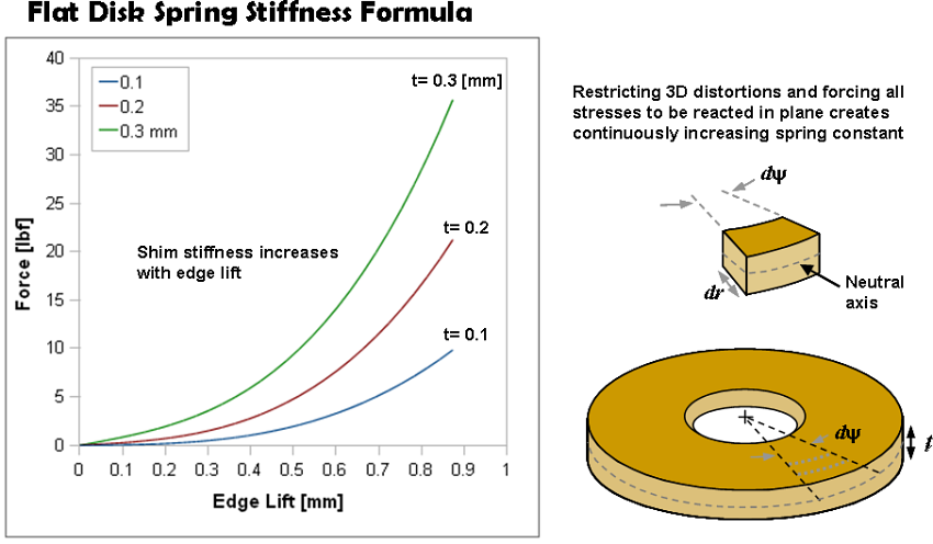
The planar force balance used in developing the flat disk deflection formula requires all forces generated during bending of the shim to be reacted within the plane of the shim. The force balance does not allow three dimensional distortions. Restricting all forces to be reacted in plane creates an artificial increase in spring stiffness and the progressive steadily increasing spring force curve shown above. Improving the accuracy of the flat disk deflection equations at high edge lift requires consideration of three dimensional distortions and out of plane motions that occur in shim stacks used in suspension systems.
_____________________________________________
Three Dimensional Shim Distortions
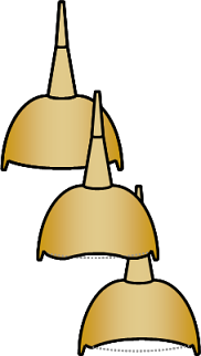
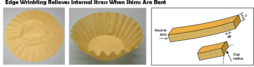
When a suspension shim is deflected from a flat disk into a cone shape the outer diameter of the shim is forced to assume progressively smaller diameters. Forcing the shim edge to a smaller diameter eventually causes the outside edge of the shim to wrinkle. The cause of edge wrinkling when a flat disk is forced into a cone shape can be easily understood studying the photo of a coffee filter below. For this "paper thin" example forcing the initial flat disk into a cone shape forces wrinkles to occur in the cone sidewall. These wrinkles conserve the initial perimeter length of the disk. As the cone is deformed into progressively smaller diameters the height of the wrinkles, or the number of wrinkles, increases to conserve the perimeter length.
Edge wrinkling at high shim lift partially relieves internal strain at shim edge.
Forces creating edge wrinkling are further amplified by Poisson's ratio. The force balance used in development of the flat disk deflection formula define a neutral bend axis through the disk. When the disk is bent the material above the neutral bend axis is compressed causing the width of each analysis element to increase. This width increase, due to Poisson's ratio, results in an increase in the inside diameter of the cone and a diameter that is greater than the neutral bend axis. This diameter mismatch produces strain in the shim material and is the cause of the steadily increasing spring constant produced by the planar force balance of the flat disk deflection formula.
Allowing the disk to bend out of plane into a cup shape, i.e. a wrinkle, increases the circumference of the inner surface of the cone resolving the diameter mismatch with the neutral axis. Wrinkles relieve the induced strain. Similarly, stretching of the material below the neutral bend axis causes the width of each analysis element to decrease reducing the external circumference of the cone. Strain generated by the reduced external circumference further reinforce bending of the element out of plane into a cupped shape. These elements of a three dimensional force balance allow strain induced in the bent shim material to be relieved through the formation of wrinkles. These wrinkles relieve strain in the bent shim material and reduce the effective stiffness of a shim.
 Three
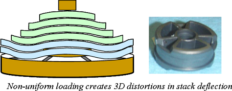
dimensional distortions occur naturally in the structure of shim stacks used in suspension
systems. On a shim stack the load is applied at the discreet locations of
the valve ports. This allows the stack to
naturally deflect into the unloaded regions between valve ports. Discreet
loading forces the stack to distort, or potato chip, into predictable
shapes with predictable wrinkle points and predictable effects on the stack
stiffness. Specifics of the distortions that occur in the stack depend on the valve port width, port spacing , applied force and
shim stack structure.
Modeling these parameters in ReStackor allows the effect of distortions on
internal strain relief to be determined as well as the effective stiffness of the stack.
Three
dimensional distortions occur naturally in the structure of shim stacks used in suspension
systems. On a shim stack the load is applied at the discreet locations of
the valve ports. This allows the stack to
naturally deflect into the unloaded regions between valve ports. Discreet
loading forces the stack to distort, or potato chip, into predictable
shapes with predictable wrinkle points and predictable effects on the stack
stiffness. Specifics of the distortions that occur in the stack depend on the valve port width, port spacing , applied force and
shim stack structure.
Modeling these parameters in ReStackor allows the effect of distortions on
internal strain relief to be determined as well as the effective stiffness of the stack.
_____________________________________________
FEA Analysis
Finite Element Analysis (FEA) packages are now available with license fees below $10k/year. Training on use of those packages typically run about three times the license fee. The need for training depends on your familiarity with FEA analysis and the CAD software typically required to define the geometry for FEA analysis.
FEA analysis gives you the capability to compute a thorough three dimensional force balance through the shim stack structure and accurately determine the stiffness. On a 3 GHz computer a thorough three dimensional shim stack analysis will require about 16 hours of computational time. That gives you the capability to analyze about 7 shim stacks per week. Computational times can be shorted by reducing the grid fineness at the expense of blurring force transmissions through the stack structure and the closing of crossover gaps; or dropping to a 2D analysis and neglecting the stress relief inherent in three dimensional stack distortions. Neither of these are viable options for an accurate analysis, and that requires 16 cpu hours.
Integration of the force transmission through the curvilinear coordinates of a shim stack is a complex problem due to the focusing of forces at the shim center. This creates a continuously changing gradient in stress through the structure that is further complicated by shim interactions in the stack and the changing shim diameters in a tapered stack configuration. Resolution of the force balance requires a fine grid structure and thousands of iterations through the computational grid to resolve the changing gradient in stress. Effects of this changing stress gradient on shim deflection was analytically solved by Almen and Laszlo in 1936 to form the Belleville spring equations. Much of the computers iteration time is spent while the FEA software rediscovers the curvilinear force balance of Almen and Laszlo over and over again at the start of each iteration cycle.
Tuning a shock absorber shim stack typically requires analysis of three or four shim stack configurations evaluated over a range of suspension velocities to understand your tuning options. The 16 hour computational time of FEA analysis for a single shim stack at a single applied force results in a requirement of weeks of computational time to complete a comparison for a handful of shim stacks evaluated over a range of suspension velocities. This computational time makes FEA analysis generally impractical for real suspension tuning work.
![]()
ReStackor Shim Stiffness Relationships
ReStackor calculations have been specifically formulated for analysis of shim stack structures used in suspension systems. The calculations integrate Hooke's law and Young's modulus of elasticity through the curvilinear coordinates of a shim to determine shim stack stiffness and account for three dimensional effects of stack distortions. The distortions "potato chip" the stack and result in an effective stack stiffness that is much softer than predicted by the ridged planar force balance of the flat disk deflection formula and Belleville spring equations.
-
Belleville springs produce a digressive spring stiffness curve due to "oil canning" forces created when the initial cone shape of a Belleville spring is crushed into a flat washer. These "oil canning" forces do not exsist in the reverse process when a flat washer is deflected into a cone shape.
-
Deflected disk equations are derived from a planer force balance requiring all forces to be reacted within the plane of the disk. Restricting three dimensional distortions and the attendant stress relief results in a artificial increase in shim stiffness at high edge lift.
-
ReStackor shim stiffness relationships allow three dimensional distortions producing important differences when compared to the standard Belleville spring and deflected disk formulas:
-
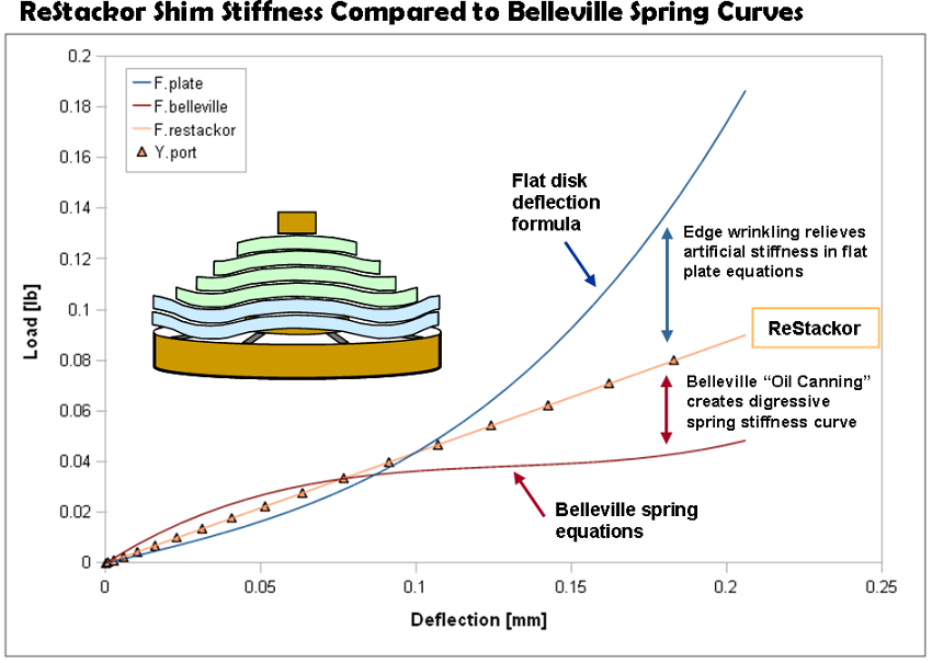
At low applied force the shim stiffness computed by ReStackor is stiffer than the deflected disk equations. The deflected disk equations are edge loaded. Shims in ReStackor calculations are loaded by fluid dynamic forces distributed over the valve port and shim stack face area. Distributed loading moves the center of pressure closer to the stack hub reducing edge lift.
-
At high edge lift the shim stiffness computed by ReStackor is much softer than the deflected disk equations. Three dimensional distortions "potato chip" the stack structure partially relieving internal stresses making the stack softer at high lift. These three dimensional distortions are not allowed within the planar force balance of the deflected disk equations resulting in an artificial increase in stack stiffness at high edge lift.
-
Specifics of the stack distortion depend on the specifics of the shim stack structure, valve port configuration and edge lift. The comparison above demonstrates a single case.
-
_____________________________________________
High Speed Dyno Data
Conventional dynos in most suspension shops are limited to suspension velocities below 50 in/sec. Data at 50 in/sec is appropriate for tuning of most shock absorbers but inappropriate for motorcycle forks. The direct connection of a motorcycle fork to the wheel results in suspension velocities that routinely exceed 150 in/sec under even mild off-road conditions. Verifying the influence of shim stack structure distortion on the performance of suspension systems requires dyno data at velocities substantially beyond the 50 in/sec limitation of conventional dyno systems. The dyno data below at suspension velocities of 550 in/sec is very rare and important data in quantifying the effect of shim stack structure distortions on suspension performance.
As shown in the figure above, the shim stiffness computed by ReStackor is roughly half the stiffness expected by the deflected disk equations at an edge lift of 0.2 mm. This difference is caused by distortions that "potato chip" the shim stack structure. The planar force balance used in development of the deflected disk equations requires all bending forces to be reacted within the plane of the shim. This ridged planar force balance leads to an expectation of a progressive increase in shim stiffness with increased edge lift and a structural stiffness of the shim stack that is dramatically stiffer then measured in dyno tests of suspension systems.
For the stack tested in this dyno run an edge lift of 0.2 mm occurs at a suspension velocity below 50 in/sec. As the damper rod velocities advance beyond 50 in/sec the increased shim stiffness expected by the deflected disk equations results in little increase in edge lift of the stack and a dramatic increase in damping force since there is little change in flow area at the stack edge. Damping forces predicted by the deflected disk equations (green curve) rapidly increase with increasing damper rod velocity. The dyno data shows no evidence of the rapid increase in shim stiffness expected by the deflected disk equations.
Shim distortion effects computed by ReStackor verified through dyno testing. Dyno data shows slightly softer shim stack then expected.
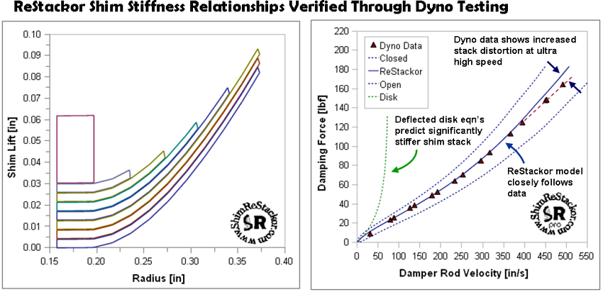
From zero to 400 in/sec the damping force predicted by ReStackor closely follow the dyno data. The shim stack distortions and attendant decrease in structural stiffness produce a damping force that closely follows the data. The above dyno data demonstrates the importance of evaluating distortions in the stack structure when estimating the stiffness of the shim stack and the well known difficulty in applying the deflected disk equations at high values of edge lift.
At suspension velocities beyond 400 in/sec the dyno data shows damping forces falling off below the values computed by ReSatckor. This fall off in damping force is evidence of further distortions in the stack structure at ultra high suspension velocities producing an effective stack stiffness that is softer then anticipated by the structural distortion relationships of ReStackor. While comparison of the current ReStackor calculations with dyno data are encouraging, the need for further improvements is indicated.
_____________________________________________
Shim Dynos
Many dyno tuners have attempted to measure the stiffness of shim stacks using fish scales and loads cells. While these methods are capable of quantifying the structural stiffness of an edge loaded stack the actual structural stiffness with a fluid dynamic load distributed over the valve port area and attendant three dimensional distortions of the stack structure produce an effective stack stiffness that is much different than what can be measured by a fish scale. Quantifying the stiffness of a shim stack for suspension tuning purposes requires the stack face to be fluid dynamically loaded and clamped in a test rig that closely mimics the environment of a suspension valve. That environment is difficult to achieve loading a shim stack with a fish scale.
