

Bump Velocity
![]()
Suspension Bump Velocity
Finally computer software to tune a shim stack
Suspension Velocity In Terms Of Bump Height And Bike Speed
When a wheel rolls over a square edge bump the hub follows an arc path. That arc path is defined by the wheel radius and bump height. The geometric relationships describing that arc path give the suspension velocity as a function of bump height using the simplifying assumption of a ridged wheel.
Average suspension velocity over a bump can be computed based on the tire diameter, bike speed and bump height.
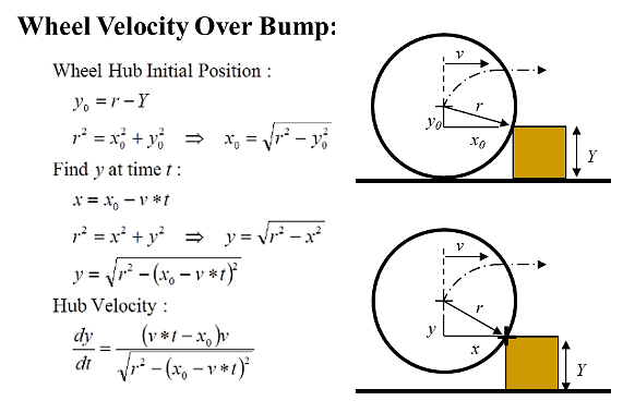
Suspension velocity is the highest at the start of a bump where the arc path is steep. Velocities asymptotically roll over as the wheel approaches the top of the bump. The figure below shows both the instantaneous and average suspension velocity as a wheel rolls over a bump.
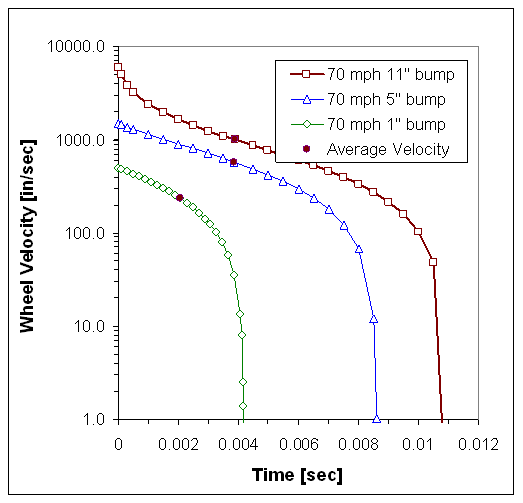
The highest suspension velocities occur at the start of a bump.
When the bump height is on the order of the hub height suspension velocities become extremely high due to the near vertical hub path. If cavitation is going to occur in a shock, it will occur at the start of the bump where the suspension velocities are highest and the gas reservoir pressures are low.
![]()
Average Suspension Velocity Over A Bump
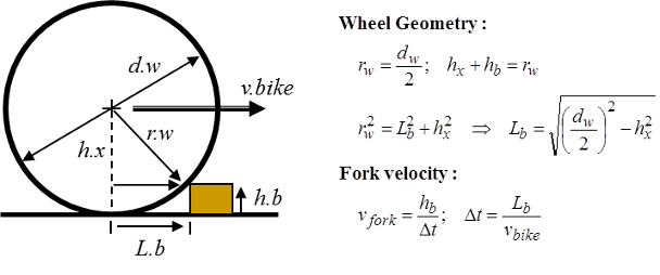
The "average" suspension velocity over a bump makes things a little simpler. Average velocity is determined by the bump height and distance traveled:
Average suspension velocity computed from the bump height (h.b) and bike speed (v.bike).
The ridged wheel assumption can be partially relaxed by assuming perfect tire compliance and subtracting 1.5 inches, or whatever, from the bump height. That brackets the range of suspension velocity from perfect compliance to the no compliance ridged wheel case.
An example: A three inch bump hit at 10 mph produces a suspension velocity of 60 inches/sec. If you have 12 inches of suspension travel the suspension would blow through its stroke in about 0.2 seconds.
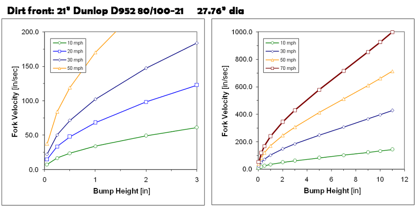
Average suspension velocities for a 21" dirt knobby as a function of bike speed and bump height
At higher speeds, the right hand figure, a 3 inch bump at 50 mph results in a suspension velocity of 300 inches/sec. This would blow through a 12 inch stroke in about 0.04 seconds. Suspension bump velocities are substantially higher than the suspension movements produced rolling over small bumps at low speed or the motions occurring when throwing your bike down into a corner.
Suspension velocities vs bump height for different wheel diameters are on the ReStackor web site: www.ShimReStackor.com/suspension-velocity.htm
-
-
21" fronts wheel
-
19" front wheel
-
-
-
17" diameter
-
18" diameter
-
19" diameter
-
-
-
16" diameter
-
17" diameter
-
8" diameter
-
-
-
17" diameter
-
18" diameter
-
-
-
26" diameter
-
29er
-
![]()
Whoop Velocities
Whoop spacing and heights vary dramatically. For purposes of bounding the range of suspension velocities the following assumptions are made: Whoop spacing of 15 feet, bike speed of 30 mph and suspension compression over the last 1/3 of the whoop spacing.
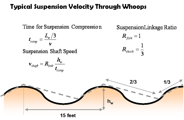
Those assumptions give a fork suspension velocity of 150 in/sec for a 16 inch whoop hit at 30 mph. Assuming a 3:1 link ratio the shaft speed on the shock would be around 50 in/sec.
Higher shaft velocities obviously occur at faster bike speeds or on larger whoops. The above gives a ball park estimate but the specifics are going to depend on the bike you are tuning, the shock linkage ratio, bike speed and whoop spacing.
If you need a better estimate high speed movies are an excellent method for estimating suspension travel and wheel velocities in the whoops. Videos also provide some good information on the interaction of the fork and shock while the bike is in the whoops.
![]()
Rebound Stroke Maximum Suspension Velocity
Maximum velocities in the rebound stroke occur when the wheel is un-weighted. Rebound velocities can be estimated directly from F= ma by balancing the spring force, air spring force and damping force in the rebound stroke against the accelerating mass of the wheel.
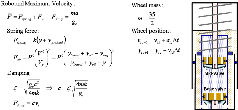
Stroke depth sets rebound peak velocity. The calculations below start with the suspension fully compressed. As the suspension extends through the rebound stroke spring force reduces while damping force increases as the wheel accelerates to higher velocities. As the suspension approaches velocities of 150 to 200 in/sec the decrease in spring force as the suspension approaches full extension causes the wheel to decelerate.
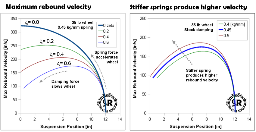
Peak rebound velocities range from 150 to 200 in/sec for a typical MX suspension setup..
Damping rates in the rebound stroke are typically tuned to operate just short of suspension packing. This allows the spring to absorb the bump energy during compression and the suspension to dissipate that energy in rebound. Tuning rebound to operate just short of packing produces the maximum energy dissipation stabilizing the bike. Higher fork oil levels or stiffer springs store more energy and require stiffer rebound damping to dissipate the higher stored energy.
