ReStackor Web


User Manual

  Input file

    Needle Geom

  Output file

  Bump Velocity


ReStackor User Manual

Finally computer software to tune a shim stack

ReStackor Inputs

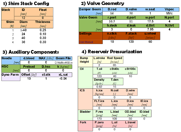
There are four sections to the ReStackor input file:

  • Shim stack configuration

    • Lists the diameter and thickness of each shim. The first shim is on the valve face.

  • Damper Geometry

    • Parameters defining the shock body and damper rod diameter. 

  • Valve Port Geometry

    • Dimensions of the valve port and bleed circuits.

  • Settings

    • Clicker position, oil viscosity, oil temperature and the maximum suspension velocity for the current calculation. 

Each ReStackor input parameter defines a geometric dimension of the shock that can be tuned and modified to control the damping force curve .

ReStackor outputs are defined here .

ReStackor Spreadsheet Operation

ReStackor inputs have been purposely designed to use simple geometric inputs you can easily measure in your garage to setup ReStackor for anything from mountain bikes, sport bikes, mx bikes or trophy trucks.
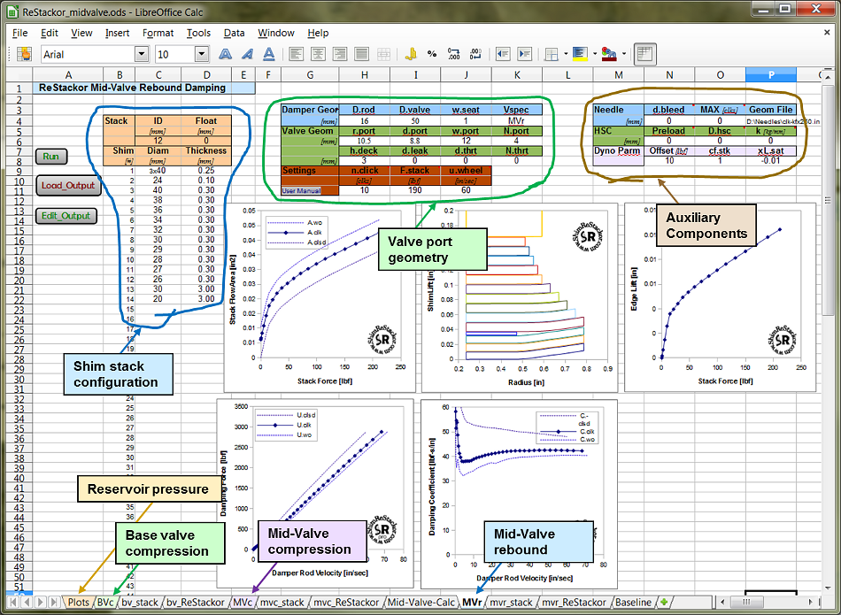
  • Run Button

    • Launches the ReStackor code. Warnings will be posted in the popup execution window if there are any errors in the inputs.

  • Load Output Button

    • Loads calculation results into the stack and ReStackor tabs of the spreadsheet. All of the plots in the spreadsheet are updated with the new calculation results.

  • Edit Output Button

    • Opens the ReStackor output file in notepad.
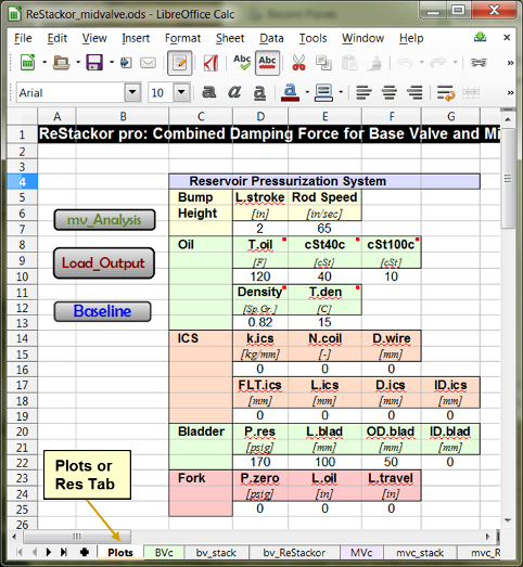
Macros in the ReStackor spreadsheet write the calculation inputs to a file. The macros are hard wired to find the inputs at the specific cell locations shown above. Because of the hard wired references you cannot move the inputs around on the worksheet. It is a good idea to have a backup of the ReStackor spreadsheet incase you muck something up on the one you are working on.

You can add another worksheet, or "tab", to the ReStackor workbook for making your own calculations. That new worksheet needs to be added after the last tab in the workbook. On that new worksheet you can add data to any cell you want, reference data on other tabs and manipulate the calculation outputs anyway you want. Only the "Plots", "stack" and "ReStackor" worksheets are accessed by the macros.

Shim Stack Configuration

The stack configuration in columns C and D list the diameter and thickness for each shim in the stack. Shim 1 is on the valve face. Definitions of each input parameter is given below.


  • ID [=] The inside diameter of the shims in millimeters, cell C6. All shims in the stack have the same inside diameter.

  • Float [=] Stack float, cell D6. The gap in millimeters between the first shim and valve face, usually zero. 

    • Positive values of float lift the stack off of the valve face using the classic definition of float. 

    • Negative values of float preload the stack for modeling of digressive damper valves with a dish or lip preloading the stack.

  • Shim Stack Configuration : Cells B9 through D58.

    • Shim # [=] Column B. Up to 50 shims can be input. If you only need 10 shims leave the rest of the cells blank. 

    • Split ring shims are entered by repeating the shim number twice as shown in the example. 

    • Diam [=] Column C. Shim outside diameter in millimeters.

    • Thickness [=] Column D. The thickness of each shim in millimeters.

    • Don't forget to enter the clamp shim at the end of the stack.

Stack preload, Float and Split Ring Shims

The stack can be preloaded using a dished valve face, a lip on the valve seat,  or a ring shim (also know as a split shim). Preload from a dished face or edge lip is modeled in ReStackor using negative values of float in cell D6. A ring shim is input by repeating the shim #  in column D6. The first entry specifies the centering shim outside diameter and the second entry specifies the ring shim diameter and thickness. The example above illustrates inputs for a split ring shim calculation.

Damper Geometry


The damper geometry section specifies the basic dimensions of the shock absorber. There are four parameters:

  • D.rod [=] The shock absorber damper rod diameter in millimeters.

  • D.valve [=] The inside diameter of the shock absorber body in millimeters.

  • w.seat [=] The seat width of the valve ports in millimeters. 

  • Vspec [=] The keyword Vspec specifies the stroke. There are three strokes:

    • BVc [=] Base valve. The compression damping valve.

    • MVr [=] Mid valve rebound stroke.

    • MVc[=] Mid valve compression stroke.

    • Ukey, Ckey [=] The Vspec keyword is also used to extract your user ID or enter a ReStackor code key as discussed below.

Suspension Stroke (BVc, MVr, MVc)

There are two types of valves in suspension systems: mid-valves and base-valves. A base valve is generally located on the opposite end of the shock from the damper rod entrance. As the damper rod is forced into the shock body, fluid is forced out through the base valve. Since the damper rod has a small diameter the flow rate through the base valve is low. The base valve is usually used for compression damping and is specified in ReStackor by setting the Vspec keyword to BVc.

A mid-valve is located on the end of the damper rod. As the damper rod is forced into the shock fluid is forced through the mid valve to fill the volume behind the mid-valve. On compression the entire face of the mid-valve is pressurized. On rebound only the annulus between the damper rod and valve OD is pressurized. Due to the difference in pressurized face area the forces generated during compression and rebound are different. The keywords MVc (mid-valve compression) and MVr (mid-valve rebound) differentiate the compression and rebound stroke in ReStackor calculations. 

User Key

ReStackor also uses the Vspec keyword to extract your user key and enter your code key. To extract your user key set the Vspec keyword to Ukey, hit the run button and the pop up execution window will shwo your user key. 

When you purchase a ReStackor code key from PayPal you will need to enter your user key. After PayPal collects your credit card info the check out confirmation page has a prompt "--- CLICK Here to enter your user key". Click on the prompt and enter your user key, your companion code key will then be emailed to you.

  • Vspec keywords Ukey and Ckey:

    • Ukey [=] The pop-up code execution window will display your user key ID. You will need this key to purchase a code key from PayPal.

    • Ckey [=] The pop-up code execution window will prompt you to enter your code key. 

Valve Geometry

The valve geometry section describes the dimensions of the valve port.

  • r.port [=] The radial distance from the valve center to the inside edge of the valve port in millimeters. This parameter defines the inner radius of the shim stack face pressurized by the valve port. 

  • w.port [=] The circumferential width of the valve port in millimeters. W.port is measured at the outer edge of the port and is the width from the inside edge to inside edge of w.seat. Large values of w.port increase the flow area at the stack perimeter and reduce the valve flow resistance.

  • d.port [=] The radial distance from the inside to outside edge of the valve port in millimeters. This parameter, coupled with w.port, describes the flow area of the valve port. The sum of r.port, d.port and w.seat should be less than or equal to the valve diameter. If not, the code will kick you out with an error message.

  • N.port [=] The number of valve ports. The Honda and Marzocchi valves shown above have four ports. The KTM valve has three.

  • d.bleed [=] Throat diameter of the clicker bleed port where the clicker needle meters the flow. More information on setting d.bleed is discussed below in the setting of MAX.clks.

  • d.leak [=] The valve port leak jet diameter. Valves using a leak jet typically have only one jet on one port. If a valve has multiple leak jets the "effective" single jet diameter is [d.leak= sqrt(N.jets) d.jet] where N.jets is the sum of all leak jets on all of the ports on one valve.

  • d.thrt [=] The diameter of any flow restriction in the valve port. For free flowing valves, like the KTM valve above, d.port and w.port define the valve port flow area, since there is no restriction D.thrt is set to zero. For valve ports with flow restrictions, like the Honda and Marzocchi valves above, D.thrt defines the minimum flow area of the valve port. 

  • N.thrt [=] The number of valve port restrictions. For the Honda and Marzocchi valves above each port has one throat restriction so both N.port and N.thrt are equal to four. In general N.thrt and N.port will have the same value. ReStackor uses the separate input for N.thrt to handle the special case where multiple side ports feed one valve port.

The parameters d.port, w.port and N.port define the flow area of the valve port. The additional parameters D.thrt and N.thrt handle the special cases of flow restrictions in the valve port. Normally the valve port is fed by the annular slot between the shim stack and valve body. The flow area of this slot is typically much larger than the valve port producing no flow restriction. For special cases where the valve port inlet or valve itself has a flow restriction the parameters N.thrt and D.thrt allow the restriction to be modeled. The parameters N.thrt and D.thrt can also be used to model valve that use multiple side ports to feed a single valve port. 

Settings

The settings section describe the clicker position and suspension velocity for the calculation. 

  • n.click [=] The clicker setting. n.click specifies the number of clicks out from the closed position.

  • SAEwt [=] The shock absorber oil viscosity in terms of SAEwt. The relationship of SAEwt and cSt@40c used by ReStackor is given here.

  • T.oil [=] The shock absorber oil temperature in Fahrenheit. The effects of oil temperature on viscosity is modeled in ReStackor using using the Andrade relationship.

  • MAX.clks [=] The number of adjuster clicks from closed to full open. To reach full open the needle tip must be a distance of h.wo above the bleed port. The number of clicks to this position can be measured directly or estimated from the NDL.clks needle position. 

  • The default ReStackor bleed circuit needle is a conical needle with a tip diameter equal to 1/2 of the bleed port throat diameter. Other needle shapes can be modeled by setting up an input table describing the needle diameter as a function of clicker positions . Instructions for setting up a clicker table are here .

  • F.max [=] The maximum force to be applied to the shim stack face. Shim ReStackor calculations display the stack structure, compute the shim edge lift and stack face flow area at forces up to F.max. F.max is in pounds force.

  • u.wheel [=] The maximum wheel velocity in inches per second. ReStackor pro calculations compute the damping force as a function of suspension velocity up to the value specified by u.wheel. If the maximum wheel velocity produces a shim stack force greater than F.max additional calculations are made internally to compute the stack deflection and flow area. Decoupling F.max and u.wheel in ReStackor allows the stack structure to be displayed at a low applied force, like examining where a crossover gap closes, while computing the damping force of the suspension at a much higher suspension velocity.

The relationship of bump height, bike speed and suspension velocity for different wheel sizes is given here. With an estimate of the suspension velocity, say a three inch bump hit a 30 mph, you can design crossover gaps, backing shims and the stack taper to produce a specific damping forces at the suspension velocity produced on a given bump height. 

ReStackor Input File

ReStackor inputs have been purposely designed to use simple geometric dimensions you can easily measure in your garage. Simple inputs coupled with physics based analysis allows input files to be easily setup for anything from mountain bikes, street bikes, MX bikes or trophy trucks. Modeling damping performance using basic physics allows ReStackor calculations to be setup to model virtually any shock.

The capability to see the shape of the damping force curve produced by the shock gives you the capability to relate what you "feel" from the suspension to the damping performance of the shock. Modifying the shim stack and numerically investigating the effects of crossover gaps, backing shims, stack preload, oil viscosity and clicker settings gives you the capability to modify the damping force curve shape, change the "feel" of the shock and tune your suspension far beyond the limits previously possible.

Simple inputs - thorough analysis - practical results. ReStackor creates a new era in suspension tuning.