

Tuning Basics
Sample Applications

ReStackor Sample Applications
Finally computer software to tune a shim stack
Cavitation Limits in a Bladder Pressurized Shock
The ReStackor_midvalve.xls spreadsheet makes motorcycle suspension tuning of a mid-valve setup easy. The spreadsheet determines the combined damping force produced by the base and mid-valve allowing you tune the shim stack configuration of each valve and control cavitation limits of the suspension.
For an MX mid-valve suspension setup there are three distinct regions in the combined damping force curve. ReStackor pro gives you the capability to understand the influence of each valve in each region, tune damping forces in that region and control the suspension velocities where damping forces transition from one region to the next.
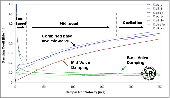
ReStackor pro gives you the capability to understand the influence of base valve and mid-vale damping rates on the shape of the damping force curve and tune damping forces over the entire range of suspension speeds.
ReStackor pro calculations determine suspension cavitation limits, the suspension velocity where cavitation initiates, the magnitude of the cavitation event and the performance of the suspension when driven beyond the cavitation limit. This gives you the capability to tune the stiffness of the base valve shim stack, mid-valve shim stack, mid-valve float and bladder pressurization systems to control damping, cavitation limits and the suspension performance over the entire range of operation. ReStackor pro handles all of these calculations internally allowing you to simply click a button to determine the suspension performance.
![]()
Determination
of Cavitation Limits 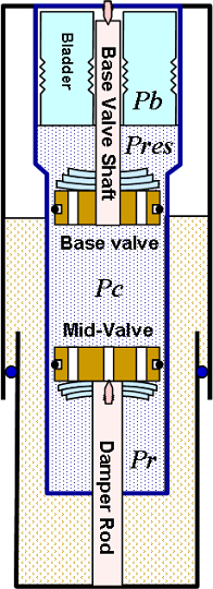
Suppressing cavitation simply requires pressures in the shock to be greater than the fluid vapor pressure. Bladder pressurization systems prevent cavitation by back pressuring the fluid circuits to maintain pressures above the cavitation limit. The pressure in the rebound chamber is defined by:
Controlling cavitation requires tuning the base valve shim stack stiffness, mid-valve stiffness, stack float, and bladder system to all simultaneously operate within the cavitation limits. When tuning by the seat-of-the-pants simultaneous control of multiple parameters is a near impossible task. ReStackor makes this process much easier. With ReStackor modeling the physical flow processes occurring within the guts of the shock it is a simple mater to spread those components out on the table, examine the physical flow processes occurring through each component and tune those components to all operate within the cavitation limits (more).
With only atmospheric pressure in the bladder the rebound chamber is driven to the cavitation at a suspension velocities of 100 in/sec. Pressurizing the bladder to the typical condition of 150 psig extends the cavitation limit to a damper rod velocity of 230 in/sec. Use of a bladder to pressurize the fluid circuits more than doubles the operating range of the shock.
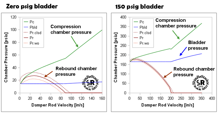
Pressurizing the bladder system in a shock keeps the rebound chamber from cavitating.
When damper rod velocity is driven beyond the cavitation limit excess fluid that can not pass through the mid-valve is forced out through the base valve. The cavitation driven flow surge forces more fluid through the base valve into the fluid reservoir resulting in a pressure increase in both the compression chamber and shock fluid reservoir, both of these effects are evident in the above figure. Elevated compression chamber pressures caused by the cavitation flow surge increase the pressure on the face of the mid-valve and partially heal the cavitating flow. The interaction of the cavitation driven flow surge with the bladder pressurization system is fully modeled in the cavitating fluid volume balance of ReStackor pro (more).
Occurrence
of the cavitation driven flow surge can be observed in this Roehrig
cavitation video through movement of the chamber separation plate.
The video also demonstrates the remarkable ability of suspension fluids
to nearly instantly recover from severe cavitation with no residual
foaming.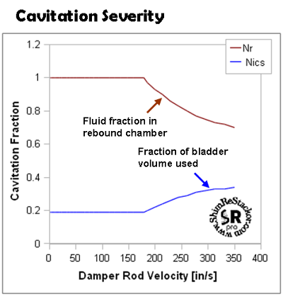
Cavitation Severity
The ReStackor fluid volume balance tracks the fraction of rebound chamber volume filled with fluid during cavitation and reports that parameter as Nr. When cavitation initiates the fluid volume faction falls below 1.0. Presence of the cavitation bubble during the start of the rebound stroke results in zero rebound damping while the cavitation bubble collapses. The ReStackor Nr parameter tells you the size of the cavitation bubble and fraction of the rebound stroke lost due to cavitation. For the example shown at 350 in/sec the cavitation bubble occupies 30% of the rebound chamber volume and will result in the first 30% of the rebound stroke producing no damping while the cavitation bubble collapses.
The ReStackor Nics parameter tracks the fraction of the bladder volume used over the stroke. For the 4" suspension stroke used in this example 34% of the bladder volume is used. Smaller bladder volumes result in more compression over the stroke at higher reservoir pressures.
Calculation Accuracy
Calculation of cavitation limits depends on small differences in large numbers. If the computed base valve pressure drop is off by 10 psi the impact on overall damping force is small. On the other hand, if the base valve pressure drop is 10 psi low and the mid-valve pressure drop is 10 psi high the 20 psi swing in pressure has a large impact on evaluation of cavitation limits. Due to this sensitivity it is unrealistic to expect ReStackor to produce exact answers in a cavitation environment. Your ability to implement and use ReStackor for control and tuning of cavitation depends on your ability to implement the art of suspension tuning ( more ).
![]()
Bladder Pressure and Volume
Evaluating damper performance under cavitating or non-cavitating conditions is a simple task using ReStackor. The process requires creating a ReStackor input file to describe the base valve and mid-valve configuration, then clicking on the mv_analysis button to plot the results.
For operation of the shock below the cavitation limit the damping force produced is simply the sum of the base and mid-valve damping force. Above the cavitation limit damping force is altered by the cavitating flow limit of the mid-valve and interaction of the cavitation driven flow surge with the reservoir pressurization system and flow rates through the base valve. ReStackor pro models all of these effects making evaluation of cavitation limits a simple task of interpreting the plots generated by the calculations.
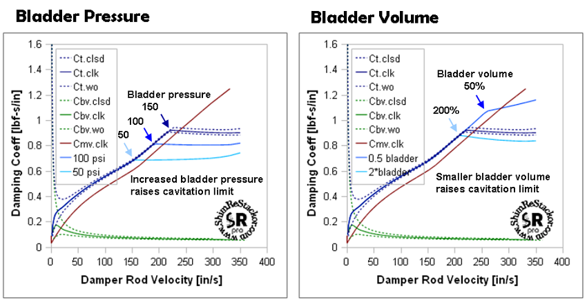
Increasing bladder pressure or altering bladder volume changes cavitation limit.
Pressures produced by the bladder act directly on the shock damper rod area producing a force acting to extend the shock toward full extension. Increased bladder pressures increase that force. The force is present under both the shock compression and rebound stroke making the bladder pressure force a spring force not a damping force. ReStackor is focused on modeling of damping forces, so this spring force produced by bladder pressurization is ignored. For this reason the damping forces produced below the cavitation limit are identical for the 50, 100 and 150 psi bladder pressures.
Once driven beyond the cavitation limit flow rates through the mid-valve are limited by the cavitating pressure drop. This limit reduces the damping forces the shock can produce. For the above example the shock produces a progressive damping profile with a progressive increase in damping coefficient (damping force/rod velocity) up to the cavitation limit. Above the cavitation limit the flow limitation of the mid-valve results in a near constant damping coefficient and a linear increase in damping force with further increases in suspension velocity.
Increasing pressures in the bladder of a shock increases the suspension velocity required to cavitate the mid-valve. For the example configuration increasing the bladder pressure by 50 psi increases the cavitation velocity by approximately 40 in/sec. A similar effect can be achieved by reducing the bladder volume. Smaller bladder volumes undergo more compression resulting in higher reservoir pressures and extended cavitation limits.
![]()
Base Valve Stiffness
Increasing the base valve shim stack stiffness increases low speed damping. The increased flow resistance through the base valve also increases pressures in the compression chamber of the shock and the damper rod velocity required to cavitate the mid-valve. For the example shown increasing the base valve shim stack increases the cavitation velocity by about 10 in/sec. A small effect.
Increasing the base valve shim stack stiffness increases pressures in the shock compression chamber (Pc) and the shock absorber cavitation velocity limit.
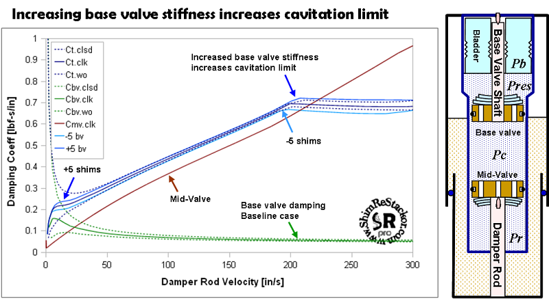
Exploiting the influence of the base valve flow resistance on mid-valve cavitation requires larger changes in the base valve flow resistance. Large changes in the base valve flow resistance coupled with simultaneous reduction of the mid-valve flow resistance allows cavitation limits to be altered while maintaining the same overall damping force. An example ReStackor calculation demonstrating that process is included in the ICS cavitation example ( more ).
![]()
Mid-Valve Stiffness
Increasing the mid-valve shim stack stiffness increases the damping force through the mid-speed range. The higher flow resistance through the mid-valve causes the rebound chamber to cavitate at a lower suspension velocity. For the example shown the cavitation velocity is reduced by about 15 in/sec.
Softening
the mid-valve shim stack produces the opposite 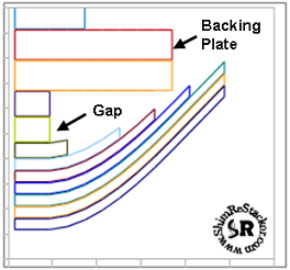 effect.
But, there are other parameters to consider. In the example shown softening the shim stack results in the
shim stack hitting the backing plate at a suspension
velocity of approximately 140 in/sec. The backing shims limit the shim
stack deflection and
result in little reduction in damping force or change in the cavitation
velocity for the softer shim stack.
effect.
But, there are other parameters to consider. In the example shown softening the shim stack results in the
shim stack hitting the backing plate at a suspension
velocity of approximately 140 in/sec. The backing shims limit the shim
stack deflection and
result in little reduction in damping force or change in the cavitation
velocity for the softer shim stack.
The capability of ReStackor to diagnose simple problems like this can save you a huge amount of time in tuning a suspension over the old cut and try method. Here the deflection limitation of the softer mid-valve shim stack is easily spotted in the damping force curve and the shim stack deflection plot of ReStackor. Understanding the cause allows the effect to be simply remedied using a larger gap shim in the stack.
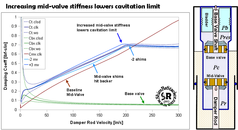
Stiffening the mid-valve shim stack increases mid-speed damping rates and causes the shock to cavitate at a lower velocity.
For the above examples, changing the mid-valve shim stack stiffness has little effect on low speed damping rates. As long as an appropriate value of stack float is used mid-speed damping rates can be tuned through modifications to the mid-valve stack stiffness without influencing low speed damping rates. The capability of ReStackor to identify the influence of each component in the shock gives you the capability to identify the component controlling a specific damping range and tune that component to achieve the desired damping force curve.
The capability to run and understand these "what if" scenarios in software gives you a far better understanding of suspension operation than could be obtained through months of seat-of-the-pants hacking trying to identify the difference in damping between mid-valve float and stiffness.
![]()
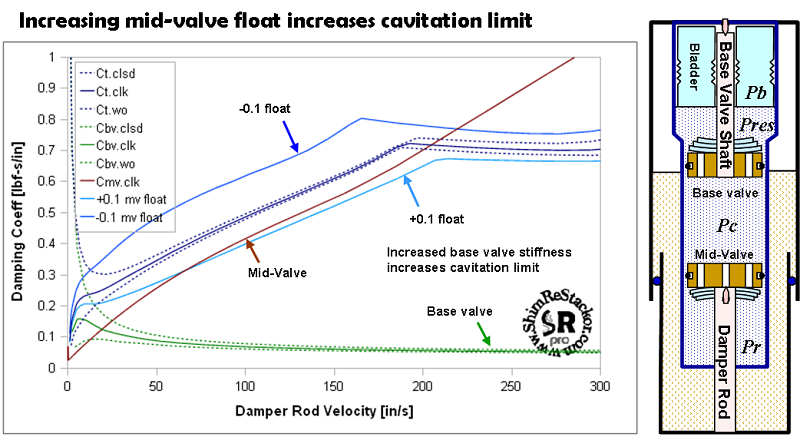
Mid-Valve Float
The increased mid-valve pressure drop caused by decreased float on the mid-valve reduces the cavitation velocity by approximately 70 in/sec. Changing the mid-valve float also effects low speed damping. Due to the interaction of mid-valve float with damping rates over the entire range of suspension speeds, care is needed when setting or adjusting float on the mid-valve.
For the example shown decreasing the mid-valve float by 0.1mm completely eliminates the linear portion of the low speed damping range. Reduced float forces the suspension into a progressive damping profile and results in cavitation of the system at a lower suspension velocity.
Small changes in mid-valve float can produce a large change in damping rates and cavitation limits of the mid-valve.
![]()
Suspension Cavitation Limits
The capability of ReStackor to compute pressure drops across suspension valves provides the fundamental capability needed to understand and tune cavitation limits. The fluid volume balance used in ReStackor gives the information needed to understand the influence of bladder systems on cavitation limits, the magnitude of cavitation events and the influence of cavitation on suspension performance. ReStackor produces simple, easily interpreted plots showing the pressures in each chamber of the shock, the onset of cavitation and the magnitude of the cavitation event. This gives you the capability to not only determine the suspension velocities where cavitation initiates but also control the magnitude of the cavitation event and the performance of the shock when driven beyond the cavitation limit.
ReStackor gives you the capability to tune each component of the shock for control of cavitation limits:
-
Stiff mid-valve shim stacks can drive the rebound chamber into cavitation during the compression stroke. ReStackor gives you the capability to tune the mid-valve stack float, stiffness and fluid reservoir pressurization system to control the cavitation velocity.
-
Base valve stack stiffness can be tuned to control the influence of compression chamber pressures on cavitation limits.
-
Bladder pressure can be tuned to control the suspension velocity where cavitation initiates.
-
Bladder volumes can be tuned to control recovery from cavitation deeper in the stroke.
-
-
The cavitation bubble formed in the rebound chamber results in zero rebound damping during the initial portion of the rebound stroke. ReStackor gives you the capability to quantify the size of the cavitation bubble and tune the suspension components to control the magnitude of rebound damping loss.
The simple physics based models of ReStackor give you the capability to understand the influence of each component of the shock, tune that component and control the influence of that component on the damping rates produced by the system across the entire range of operation. Understanding the component influence and system operation gives you the ability to tune your suspension far beyond the limits previously possible.
ReStackor defines a new era in suspension tuning.
