


Cavitation Limit
ReStackor pro Fluid Dynamics
Cavitation Control At High Suspension Velocity
Controlling cavitation simply requires pressures in the fluid circuits to be greater than the fluid vapor pressure. While conceptually simple, confusion over the stiffness of shim stacks, pressure drops through the flow circuits and back pressure produced by ICS systems can make control of cavitation limits difficult. Frustrations with cavitation forced Roehrig to construct a transparent glass shock absorber for the simple purpose of demonstrating the occurrence of rebound chamber cavitation during the compression stroke in their investigation of performance failures of stock car racing shocks. The video obtained by Roehrig demonstrates three important events that occur during cavitation:
-
The rebound chamber can be driven to violent cavitation during the compression stroke.
-
The vapor bubbles formed during cavitation immediately collapse after the cavitation event. There is no significant foaming of the suspension fluid.
-
The cavitation driven flow surge created by the mid-valve pushes additional fluid through the base valve into the shock reservoir. Effects of the surge can be observed by movement of the chamber separation plate in the Roehrig video .
Cavitation
control requires tuning the base valve stack stiffness, mid-valve
stiffness, stack float, and bladder or ICS system to all simultaneously
operate within the cavitation limits of the shock. When tuning by the
seat-of-the-pants simultaneous control of multiple parameters can be a nearly impossible
task. 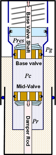
With ReStackor controlling cavitation limits of an MX mid-valve setup is a much easier task. Since ReStackor models the physical flow processes occurring within the guts of a shock it is a simple mater to spread those components out on the table, examine the physical flow processes occurring through each component and tune those components to all operate within the cavitation limits. What is often referred to as a complex interaction of cavitation is reduced to solution of a simple arithmetic relationship:
As long as the pressure in the shock reservoir and pressure drop across the base valve is larger than the mid-valve pressure drop the rebound chamber will not cavitate.
Beyond cavitation limits ReStackor pro determines the suspension velocity where cavitation initiates, the magnitude of the cavitation event and the performance of the suspension when driven beyond the cavitation limit. ReStackor pro gives you the capability to tune the stiffness of the base valve shim stack, mid-valve stiffness, mid-valve float and bladder or ICS system for control of cavitation. This gives you the capability to understand the influence of each component in the system and tune that component to control cavitation. The physics of flow cavitation are handled internally within the ReStackor pro allowing you to simply click a button and determine the suspension performance.
![]()
Calculation
of cavitation limits
The mid-valve shim stack is typically much softer than the base valve stack. The combination of a softer shim stack and mid-valve float results in low pressure drops at low suspension speeds. As suspension speeds increase the higher oil flow rates through the mid-valve result in a dramatic increase in the mid-valve pressure drop. Calculation of pressure drops through suspension valves is the central focus of ReStackor, this capability allows the valve pressure drops to be defined and the pressures in each chamber of the shock determined.
The pressure in the shock compression chamber (Pc) is defined by the pressure in the fluid reservoir (Pres) and the pressure drop across the base valve:
![]()
The pressure in the rebound chamber (Pr) is defined by the pressure drop across the mid-valve:
![]()
These two expressions define the pressures in each chamber of the shock. Plotting the chamber pressure as a function of suspension velocity clearly shows the cause of cavitation in a shock. The pressure in the shock compression chamber steadily increases as the pressure across the base valve builds with increasing suspension velocity. The pressure drop across the mid-valve increases at a faster rate resulting in a steadily decreasing rebound chamber pressure. Above velocities of 190 inches/sec the rebound chamber reaches near vacuum conditions causing cavitation of the rebound chamber.
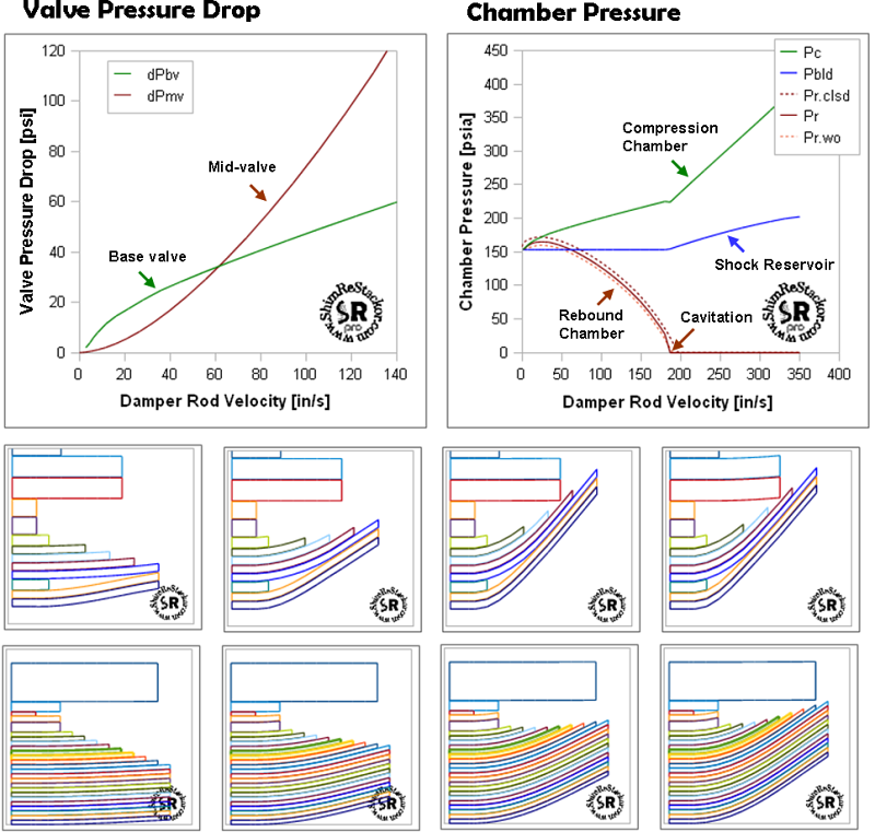
The capability of ReStackor to compute flow resistance and pressure drops across suspension valves makes calculation of cavitation limits a simple task.
![]()
Cavitating Fluid Flow Rates
When cavitated, pressures in the rebound chamber are dictated by the vapor pressure of the hydraulic fluid. Attempting to drive suspension velocities beyond the cavitation limit simply results in the flashing of more fluid and the formation of a larger cavitation bubble. Similarly, if the damper rod motion was stopped, pressures in the rebound chamber would remain at the fluid vapor pressure until enough fluid was transferred through the mid-valve to completely fill the cavitation bubble. As long as the cavitation bubble is present pressures in the entire chamber are dictated by the vapor pressure of the hydraulic fluid. This fact of cavitating flow makes calculation of flow rates a simple task. Downstream pressures are dictated by the fluid vapor pressure and the fluid flow rate is a simple function of the upstream pressure. Due to the simplicity of this calculation cavitating orifices and cavitating venturies are widely used in industry for precision metering of fluids. ReStackor uses these standard cavitating flow meter relationships to determine flow rates.
Cavitation Flow Surge
When cavitated, excess fluid that can not pass through the mid-valve is forced out through the base valve. This creates a cavitation driven flow surge pushing more fluid into the shock reservoir and increasing the back pressure produced by bladder or ICS systems. Increased backpressure and increased pressure drop across the base valve both act to increase pressures in the shock compression chamber and partially heal the cavitating mid-valve flow. These effects are fully modeled in the ReStackor fluid volume balance. Effects of the cavitation driven flow surge cause an increased rate of pressure rise in the reservoir and compression chamber when the shock is driven beyond the cavitation limit. These effects can be seen in the ReStackor pressure plot below.
Effects of the cavitation driven flow surge in pushing more fluid into the shock reservoir can also be seen in the Roehrig cavitation video through the movement of the chamber separation plate when the rebound chamber is cavitating.
Cavitation driven flow surge through base valve into shock reservoir cause an increase in compression chamber and reservoir pressures when the shock is driven beyond the cavitation limit.
The cavitation flow surge can stroke ICS chamber pistons beyond expected limits and potentially damage plastic pistons used in some ICS systems. ReStackor computes the magnitude of the cavitation driven flow surge and the fraction of ICS stroke used which allows you to tune the suspension components to control the cavitation flow surge and the stroke limits of the ICS piston.
![]()
Fluid Temperature Effects
Cavitation limits are controlled by the fluid vapor pressure. ReStackor uses the Antoine vapor pressure equation to determine fluid temperature effects on vapor pressure and the Andrade relationship to determine temperature effects on fluid viscosity. These relationships allow you to estimate effects of fluid temperature on valve pressures drops and cavitation limits.
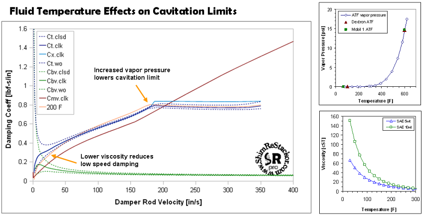
Increased temperature reduces the oil viscosity and low speed damping effectiveness, the increase in fluid vapor pressure lower the cavitation velocity.
For the 5 wt oil used in this example increasing the fluid temperature results in a substantial loss in low speed damping due to the viscosity reduction. At high speed the slight increase in vapor pressure at 200 F results in little change in the cavitation velocity. These results, of coarse, depend on the tuning of the suspension and the pressurization system used in the shock. Shocks with low reservoir pressures are more sensitive to changes in fluid temperatures.
![]()
Suspension Cavitation Limits
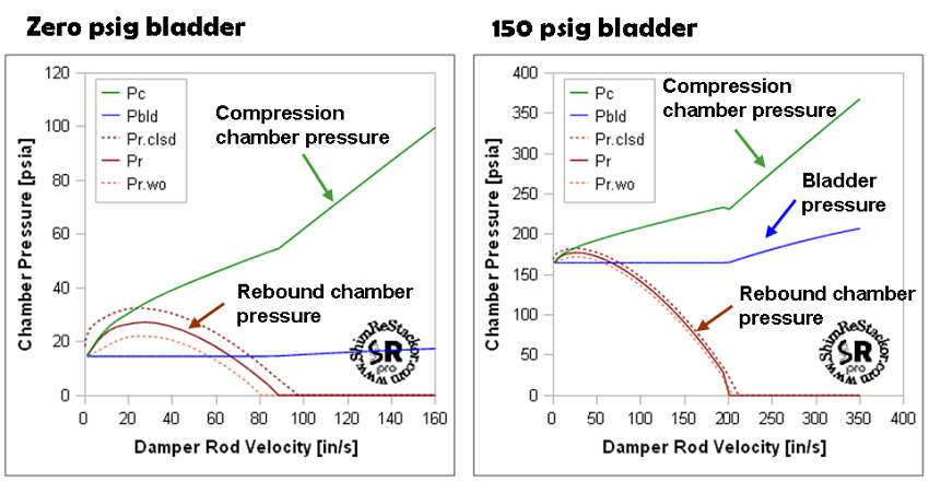
The fundamental capability of ReStackor to compute pressure drops across suspension valves gives the information needed to control and understand cavitation limits. Combining ReStackor with a simple fluid volume balance allows the magnitude of cavitation events to be quantified and the effectiveness of bladder or ICS pressurization systems in suppressing cavitation to be determined.
The capability of ReStackor to model the internal components of the shock gives you the capability to test modifications to those components and understand the influence of each components on damping performance and cavitation. This allows you to test various shim stack and valve configurations and determine the influence of those components on pressures in each chamber of the shock and cavitation limits. Bladder pressures and the stiffness of ICS springs can be tuned for operation with and existing suspension setup or the setup can be tuned for operation with the pressurization system.
