


Fluid Volume Balance
ReStackor pro Fluid Dynamics
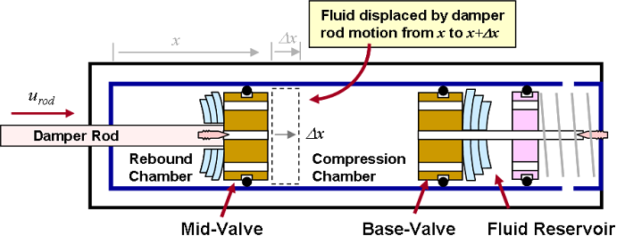
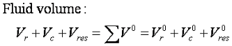
At any point in the suspension stroke the sum of the fluid volumes in the compression, rebound, and fluid reservoir add up to a constant value. Realization of this volume balance allows ReStackor to determine the volume of fluid in any chamber given the value in the other two.
Competing flow paths of the bleed circuit, base valve and mid-valve often create confusion on the flow rates through a shock especially when those flows are interacting with a bladder or ICS system. These flows are easily understood when broken down in terms of a fluid volume balance. Both cavitating and non-cavitating conditions are discussed below.
Non-Cavitating Conditions
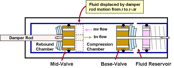
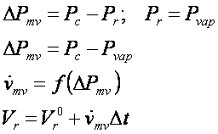
When the damper rod is driven into the shock body a volume of fluid, equal to the damper rod volume, is forced out through the base valve. This simple notion of a fluid volume balance allows ReStackor to compute the volume of fluid in the reservoir at any damper rod position under non-cavitating conditions.
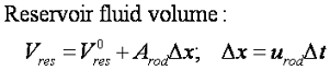
The fluid volume in the compression chamber is a simple function of damper rod position.
![]()
Mid-Valve Flow Rate, Non-Cavitating Conditions
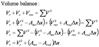
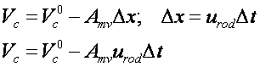
The fluid volume balances requires the the sum of the fluid volumes in each chamber of the shock to sum up to a constant value at any position in the stroke:
Combining the fluid volume balance with the expressions for the fluid volume in the reservoir and compression chamber produces an expression for the fluid volume in the rebound chamber:
The fluid volume balance gives ReStackor the capability to determine the fluid volume in any chamber of the shock at any point in the stroke. The fluid volume balance also specifies the flow rates through each circuit of the shock necessary to maintain that volume balance.
![]()
Fluid Compressibility
Suspension fluids are, by design, virtually incompressible. The basic design rules of hydraulic systems specify a fluid compressibility of 1/2% at 1000 psi. Application of this basic rule to a motorcycle fork shows a pressure spike of 500 psi produces a suspension motion of 0.1 inches. This motion, known as hydraulic surge, is inconsequential when compared to the bump height and suspension velocity required to generate a 500 psi spike. Treating suspension fluids as incompressible is a practical approach to design of suspension systems.
The more practical problems of fluid compressibility are related to dissolved gas or water resulting in foaming of the suspension fluid. Foaming is not a fluid compressibility effect, foaming is an issue created by poor design of the suspension circuits or lack of maintenance. Quality suspension fluids are capable of instantly recovering from cavitation with no residual foaming or dissolved gasses. The remarkable ability of suspension fluids to do that has been demonstrated under severe cavitation conditions in this Roehrig video.
ReStackor treats suspension fluids as incompressible. Available data shows the effect of hydraulic surge in suspension systems to be small. Roehrig has demonstrated suspension fluids are capable of recovering from severe cavitation with little residual foaming that would suspension performance in any realistic way. Treating suspension fluids as virtually incompressible is a practical approach to suspension system design and is the approach used by ReStackor.
![]()
Cavitating Volume Balance
Under
cavitating conditions, fluid flow rates through the mid-valve are insufficient
to keep the rebound chamber filled with fluid. The deficit in flow results in the
formation of a vacuum bubble in the rebound chamber. That vacuum bubble is
filled with hydraulic fluid vapor. The presence of the
cavitation bubble fixes the pressure in
the rebound chamber at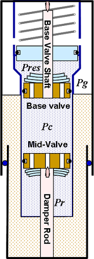 the vapor pressure of the hydraulic fluid. Forcing the damper rod beyond
the cavitation limit simply results in the
flashing of more fluid and the formation of a larger cavitation bubble,
while pressures in the chamber remain fixed at the vapor pressure of the
fluid.
the vapor pressure of the hydraulic fluid. Forcing the damper rod beyond
the cavitation limit simply results in the
flashing of more fluid and the formation of a larger cavitation bubble,
while pressures in the chamber remain fixed at the vapor pressure of the
fluid.
This fact of cavitating flow makes the calculation of fluid flow rates a simple task. Downstream pressures are fixed by the fluid vapor pressure making the flow rate a simple function of the upstream pressure. Due to the simplicity of this calculation cavitating orifices and cavitating venturies are widely used in industry for precision metering of fluids. ReStackor uses the relationships developed for cavitating flow meters to determine the mid-valve flow rate under cavitating conditions.
The fluid vapor pressure is determined using the Antoine vapor pressure equation allowing ReStackor to account for fluid temperature changes on cavitation limits. The fundamental capability of ReStackor to compute fluid flow rates as a function of valve geometry, shim stack stiffness and fluid viscosity allows ReStackor to determine the valve flow rate at the specified pressure drop of cavitating flow conditions.
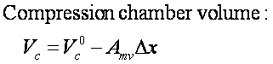
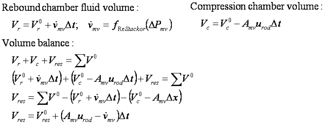
The volume of the compression chamber is specified by the damper rod position and velocity:
Combining the relationships for the compression chamber volume and mid-valve flow rate with the volume balance produces an expression for the fluid volume in the shock fluid reservoir.
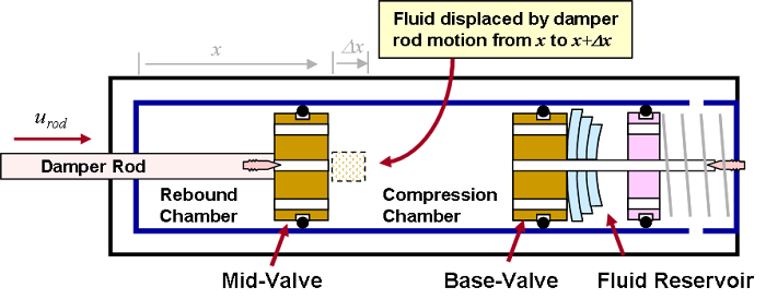
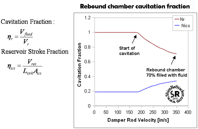
Under cavitating conditions the mid-valve is unable to deliver the fluid volume necessary to keep the rebound chamber filled with fluid. The deficit in flow results in the formation of a cavitation bubble. The volume of the cavitation bubble and the severity of cavitation is reported by ReStackor as the ratio of fluid volume to chamber volume in the rebound chamber (Nr). For the example shown the rebound chamber is 70% filled with fluid at the end of a 6" suspension stroke at 350 in/sec.
ReStackor computes the fraction of chamber volume filled with fluid (Nr) and the stroke fraction of the ICS system (Nics) relative to the coil bind length of the ICS spring.
When the mid-valve is cavitated, excess fluid that cannot pass through the mid-valve is force out through the base valve. This creates a cavitation driven flow surge into the shock fluid reservoir. The flow surge can stroke the ICS pistons beyond limits expected under non-cavitating conditions. Under extreme conditions the cavitation flow surge can damage plastic pistons used in some ICS systems. ReStackor reports the ICS piston stroke (Nics) in terms of the coil bind stroke length of the ICS spring.
Pressure Balance
The final relationship for cavitating flow requires ReStackor to determine the pressure in the compression chamber of the shock such that the pressure drop across the base valve, and the backpressure produced by the reservoir, is consistent with the flow through the mid-valve and the requirements of the fluid volume balance:
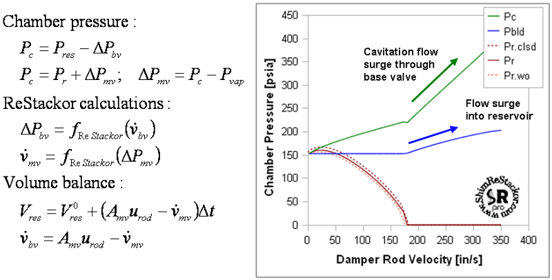
Solution of the fluid volume balance and attendant mid-valve flow limits imposed by cavitation allows ReStackor to determine the fluid flow rate, pressure drop and fluid volume in each chamber of the shock. When cavitated, flow through the mid-valve is dictated by vapor pressure of the hydraulic fluid. Excess fluid that cannot pass through the mid-valve is forced through the base valve into the shock reservoir creating a cavitation driven flow surge. The flow surge increases pressures produced by the bladder or ICS system and pressure drop across the base valve. This backpressures the shock compression chamber partially healing the cavitating mid-valve flow. The fluid volume balance and physics based definition of mid-valve cavitation limits allows ReStackor to track the cavitation driven flow surge in a natural way and define the shock compression chamber pressure that simultaneously satisfies the fluid volume balance and cavitating flow limitations of the mid-valve.
Thorough modeling of the basic flow physics ReStackor is capable of accurately computing the flow rate through each valve, modeling the cavitation driven flow surge into the shock reservoir and computing the effects of cavitation on shock absorber performance. Application of the fundamental physical flow models of ReStackor gives you the capability to tune each component of the flow circuit and determine the influence of that component on cavitation and performance limits of the shock over the entire range of suspension operation.
The combination of fundamental physical flow models, detailed component performance modeling and comprehensive integration of system performance gives you the capability to tune your suspension far beyond the limits previous possible.
