

Sample Applications

Rebound Chamber Cavitation
ReStackor pro Fluid Dynamics
-
Cavitation of the rebound chamber, during the compression stroke, causes loss of rebound damping.
-
ReStackor pro gives you the capability to:
-
Understand the cause of cavitation and the influence of each component in the shock on cavitation.
-
Determine suspension velocities where cavitation initiates.
-
The severity of cavitation.
-
The effect of cavitation on compression and rebound damping.
-
The fraction of rebound damping lost.
-
And capability to tune your suspension to control cavitation effects.
-
It
is desirable in a motorcycle suspension to have near zero spring force at the
top of the stroke to allow the fork to float over small bumps when under hard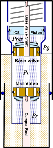 acceleration or on a hill climb. This conflicts with cavitation suppression
which requires heavy
pressurization of the fluid reservoir to prevent cavitation.
acceleration or on a hill climb. This conflicts with cavitation suppression
which requires heavy
pressurization of the fluid reservoir to prevent cavitation.
ICS systems attempt to fulfill these conflicting requirements. Near zero preload on the ICS spring fulfills the desire for low spring force at the top of the stroke but leaves the reservoir un-pressurized. Fluid transfer into the ICS chamber during the stroke engages the spring, pressurizes the reservoir and backpressures the shock circuits.
Calculation of Cavitation Limits
The flaw of an ICS system is lack of pressurization at the top of the stroke. This allows the shock to cavitate. Increased back pressure deeper in the stroke heals the initial cavitation.
The fluid reservoir pressure (Pres) is a simple function of the volume of fluid in the reservoir and the stiffness of the ICS spring:
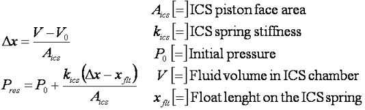
Flow resistance through the base valve is a function of the port geometry, shim stack stiffness, fluid viscosity and damper rod velocity. Computing the flow resistance through suspension valves is the central focus of ReStackor. Calculation of the pressure drop allows the shock compression chamber pressure to be determined through the simple definition:
and pressures in the rebound chamber through the definition:
These two relationships define the rebound chamber pressure as a function of the reservoir pressure, shim stack stiffness and suspension velocity. When the pressure in the rebound chamber falls below the vapor pressure of the suspension fluid the chamber will cavitate. The occurrence of rebound chamber cavitation during the compression stroke has been videoed by Roehrig. Cavitation can be large and violent.
![]()
Rebound Damping Loss
For a typical MX mid-valve setup the flow resistance through the mid-valve increases much faster than the flow resistance through the base valve. Whenever the mid-valve pressure drop is greater than the base valve pressure drop the fork is susceptible to cavitation. For the example here the suspension will cavitate at any suspension velocity above 85 inches/sec. This will occur on a 3/4 inch bump at a bike speed of 30 mph.
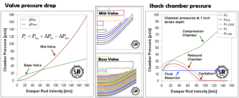
Typical mid-valve shim stack configurations result in cavitation of the rebound chamber on any bump larger than 3/4 of an inch.
When
cavitated,
pressures in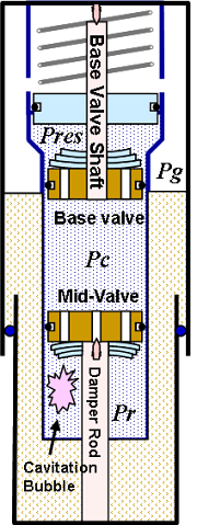 the rebound chamber are defined by the vapor pressure
of the
hydraulic fluid. If
the damper rod motion were suddenly stopped while the chamber was
cavitated, pressures in the
chamber would remain at the fluid vapor pressure until
enough fluid has been transported through
the mid-valve to completely fill the cavitation bubble.
the rebound chamber are defined by the vapor pressure
of the
hydraulic fluid. If
the damper rod motion were suddenly stopped while the chamber was
cavitated, pressures in the
chamber would remain at the fluid vapor pressure until
enough fluid has been transported through
the mid-valve to completely fill the cavitation bubble.
Loss of rebound damping
If the ICS system is unable to fill in the cavitation bubble during the compression stroke the following rebound stoke initiates with the cavitation bubble in the rebound chamber. The presents of the vacuum cavitation bubble produces no flow through the mid-valve and no rebound damping. This entire process has been videoed by Roehig.
Beyond loss of rebound damping the actual situation is even worse. When the damper rod motion stops the cavitation bubble begins collapsing. The suction force of the collapsing cavitation bubble draws fluid through the mid-valve producing a force pushing the damper rod toward full extension. Beyond loss of damping, the collapsing cavitation bubble produces a force pushing the suspension toward full extension.
![]()
Riding High In The Stroke
Excess rebound damping will cause a suspension to pack, loss of rebound damping produces the opposite effect of jacking the suspension. In addition, the forces produced by the collapsing cavitation bubble push the suspension toward full extension. The combination of these two effects push the suspension above the normal ride height producing the effect of riding "high in the stroke".
With the suspension jacked above the normal ride height, spring rates are reduced and the suspension floats over small bumps. Loss of rebound damping due to cavitation is a feature. This feature interferes with the ability of the suspension to track under hard acceleration and can cause head shake. ReStackor gives you the ability to quantify and control cavitation effects on rebound damping loss. The ReStackor fluid volume balance reports the severity of cavitation as the fraction of rebound chamber volume filled with fluid (Nr). The fraction of rebound damping lost due to cavitation is (1-Nr).
Cavitation Severity
A six inch suspension stroke at 30 mph produces a suspension velocity of 250 in/sec. For a typical MX mid-valve setup that velocity will cavitate the rebound chamber at the top of the stroke producing a fluid fill fraction of 67% and a cavitation bubble that fills 33% of the chamber volume. Deeper in the stroke, the backpressure produced by the ICS system forces filling of the cavitation bubble. For a suspension velocity of 250 in/sec a stroke depth of 11 inches is required to build the ICS backpressure necessary.
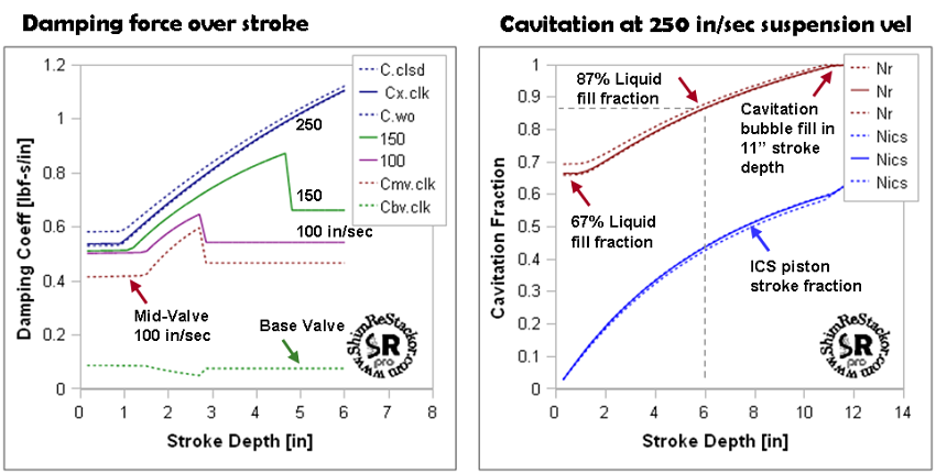
Lack of fluid circuit backpressure in an ICS chambered fork results in cavitation of the rebound chamber at the top of the stroke and large variation in damping force from the fork.
When cavitated, pressures on the back side of the mid-valve are defined by the near vacuum pressure of the hydraulic fluid vapor pressure. Pressures on the front side of the mid-valve are defined by the pressures of the ICS system. This produces a high pressure drop across the mid-valve while the cavitation bubble is filling. The system pressures act directly on the damping rod forcing the suspension to produce higher than normal damping forces.
Damping Force Variations Created by Cavitation
For the example shown damping forces vary by more than a factor of two over the stroke depth. This effect is often referred to by riders as mid-stroke harshness and is an artifact of cavitation in an ICS system. The higher damping forces generated by cavitation keep the suspension from bottoming on large hits. Forces caused by the collapsing cavitation bubble during the rebound stroke act to accelerate the un-sprung mass of the wheel into the rebound stroke. This, coupled with loss of rebound damping, assists the suspension in recovering back to the normal ride height. Mid-stroke harshness, bottoming resistance and rebound stroke acceleration are a coupled, tunable system in an ICS chambered fork. Tuning those features requires controlling cavitation through adjustments to of the base valve, mid-valve and ICS system.
ICS Piston Stroke Limits
The ReStackor parameter Nics reports the fraction of ICS piston stroke used relative to the coil bind stroke length of the ICS spring. Under severe conditions the cavitation driven flow surge into the ICS reservoir can over stroking the piston resulting in potential damage to plastic pistons used in some ICS systems. For the example here a suspension stroke of 11 inches consumes 60% of the available ICS piston stroke. ReStackor gives you the capability to tune the suspension flow circuits to control the severity of cavitation and the stroke fraction of the ICS piston.
![]()
Cavitation Bubble Control
The examples below examine the suspension performance at 180 in/sec over the coarse of the suspension stroke. Effects of ICS spring stiffens, mid-valve float and shim stack stiffness are examined by ReStackor pro calculations over the coarse of the stroke. Cavitation at the top of the stroke results in a fluid fill fraction in the rebound chamber of 75% and a cavitation bubble occupying the remaining 25% of the chamber.
ICS spring stiffness
Lack of pressurization of the shock fluid reservoir allows the rebound chamber to cavitate at the top of the stroke. Stiffer ICS springs produce higher reservoir pressures, larger pressure drops across the cavitating mid-valve and faster filling rates of the cavitation bubble. This shortens the suspension stroke depth required to closeout the cavitation bubble. Stiffer ICS springs result in higher damping forces under cavitating conditions and improve the suspension bottoming resistance. The stroke depth over which cavitation controls damping can be tuned by changing the ICS spring stiffness.
When the cavitation bubble collapses the fluid circuits flip from cavitating to non-cavitating flow. The flow condition flip negates the artificial damping force increase created by cavitation. This produces a jump in damping force at collapse of the cavitation bubble. Stiffer ICS springs amplify the magnitude of the damping force jump producing the effect of mid-stroke harshness. The magnitude and stroke depth where this occurs is completely tunable in ReStackor by controlling the ICS spring stiffness and suspension valve flow resistance.
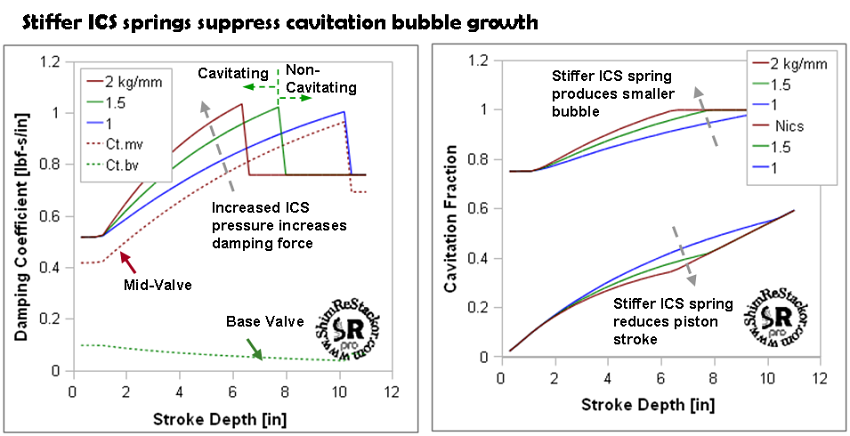
Stiffer ICS springs fill in the cavitation bubble earlier in the stroke and reduce the loss in rebound damping due to cavitation.
The stroke depth of the ICS piston is shown in the right hand figure. Softer ICS springs produce a larger cavitation bubble and a deeper piston stroke depth. For the suspension velocities used in this example none of the configurations are near the stroke limits of the ICS spring.
The size and filling rates of the cavitation bubble is shown in the right hand figure. Softer ICS springs produce a larger cavitation bubble and require a deeper suspension stroke depth to fill in the cavitation bubble. The larger cavitation bubble allows by softer ICS springs increase the loss of rebound damping and enhance the feature of riding "high in the stroke".
On a corner entrance, the suspension relies on rebound damping to fold the front end down to setup the bike in the turn. If the fork compression under braking is insufficient to produce the ICS system pressures necessary to closeout the cavitation bubble the suspension will suffer from loss of rebound damping. This loss of rebound damping allows the suspension to pop up and pop you off the outside of the turn. Whether mid-valve cavitation produces the feature of riding high in the stroke or the snake bite behavior of popping you off a turn depends on how it is tuned.
Mid-Valve Float
Decreasing mid-valve float increases flow resistance through the mid-valve and the size of the cavitation bubble formed at the top of the stroke. The larger cavitation bubble forces more fluid into the ICS chamber and the increased back pressure results in larger variations in damping force over the stroke and a larger damping force jump when the bubble closes out. The larger bubble also requires a deeper suspension stroke depth to closeout the cavitation bubble. Low values of mid-valve float amplifying mid-stroke harshness effects.
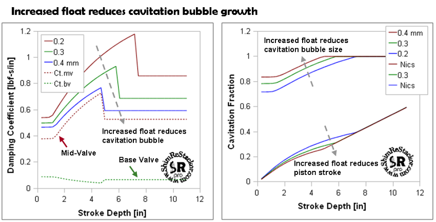
Decreasing float increases the size of the initial cavitation bubble and the fraction of rebound stroke lost due to cavitation.
Low values of stack float increase the size of the cavitation bubble and amplify the effect of "riding high in the stroke" due to the loss of rebound damping. This loss of rebound damping can also result in head shake due to lack of damping at the top of the stroke. Controlling the damping loss requires tuning of the mid-valve float to operate within the limits of the base valve flow resistance and ICS spring stiffness.
Base Valve Stack Stiffness
The suspension velocity where cavitation initiates and the size of the cavitation bubble produced depends on the difference in pressure drop between the base valve and mid-valve. Increasing the base valve flow resistance increases pressures in the shock compression chamber. This reduces the size of the initial cavitation bubble and causes the cavitation bubble to closeout earlier in the stroke.
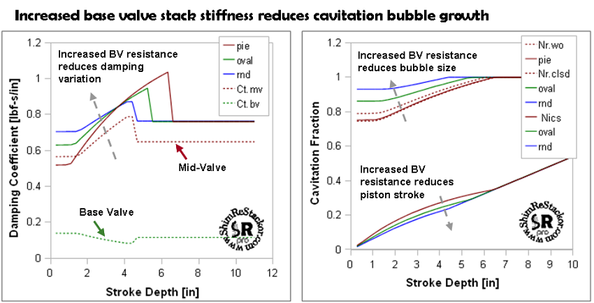
Increased stiffness of the base valve shim stack increases pressures in the shock compression chamber and reduces the severity of mid-valve cavitation.
![]()
Cavitation Behavior of ICS Chambered Forks
ICS systems in motorcycle forks produce low pressurization of the fluid reservoir at full extension of the suspension. In the whoops, impact of the whoop face at full fork extension results in the mid-valve cavitating at the top of the stroke and recovering from cavitation deeper in the stroke. The process of initial cavitation followed by recovery from cavitation deeper in the stroke produces a number of suspension ills frequently summed up as mid-stroke harshness.
ICS System Features
-
Low spring force at the top of the stroke.
-
The fork rides high in the stroke due to the loss in rebound damping.
ICS System Problems
-
Loss of rebound damping can cause the fork to popup on a turn entrance and pop you off the outside of a turn.
-
Loss of rebound damping at the top of the stroke can cause head shake under hard acceleration.
-
The process of cavitation recovery creates variations in damping force over the stroke depth and a jump in damping force at cavitation recovery.
These features are all tunable. ReStackor gives you the capability to quantify the fraction of rebound damping lost due to cavitation, the variation in damping force over the stroke depth caused by cavitation and the ability to tune the suspension components to control pressures and the severity of cavitation in the shock rebound chamber. Controlling cavitation and the overall damping force of the suspension requires simultaneous tuning of the base valve, ICS spring stiffness and mid-valve stack stiffness and float.
Simultaneous tuning of multiple parameters is an intimidating prospect for a seat-of-the-pants tuners. That process is much easier with ReStackor where you can experiment with each parameter, see the effect of that parameter on both cavitation and damping force, and simultaneously tune multiple parameters to control the level of cavitation and the overall damping rates of the suspension system. An example is here. ReStackor gives you the capability to optimize the features of an ICS system while controlling the snake bite problems of cavitation.
